Improvements to Guided Wave Focusing for Pipeline Inspection in the Field
By J Allwright and R Sanderson
Industrial Need
Guided ultrasonic waves are used to inspect tens of metres of pipeline from a single test location. In recent years, improvements have been made to the guided wave inspection procedures for pipes, including methods to predict the size and shape of flaws, and to focus the sound energy to increase sensitivity. However, the new techniques are currently only designed for simple geometries, namely straight pipes with constant wall thickness, and could therefore be ineffective in more complex tubular structures such as those with changes in thickness, attachments or weld cap geometry.
The benefits of guided wave focusing include the ability to get some semi-quantitative information about size and position of flaws. Focusing is already incorporated into some commercial guided wave systems, and there is potential for improving it. Here, guided wave focusing techniques have been investigated in situations such as pipes with weld cap geometry, pipe supports, pipe branches, or changes in thickness. A combination of finite element analysis and experimentation was used to identify, develop and validate an improved focusing capability in such situations.
Key findings
Of the four state-of-the-art guided wave focusing techniques assessed, the most successful were synthetic focusing (achieved through post-processing raw data from an unfocused test) and the analytical dispersion-removal (AD-focus) active focusing method (involving tailored inputs to different segments of the guided wave transmitting tool). AD-focusing was proven to perform significantly better and more reliably than standard active focusing.
Using FE modelling, the AD-focus method was shown to be successful in a range of set-ups, including different tool configurations (individual points, octants, multiple rings, collar gap), pipe sizes, focal angles, focal distances, and number of flexural wave modes.
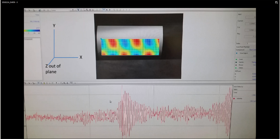
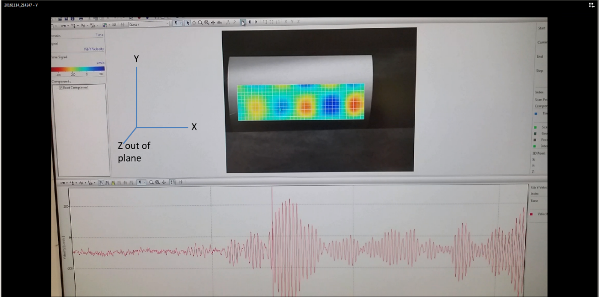
Lab-based experimental validation of the AD-focusing technique, using octant excitations and measuring the focal profile with a laser vibrometer, proved that the AD-focus algorithm could be implemented with excellent results (a significant improvement over the standard focusing which is currently implemented).
Excellent agreement was obtained between model and experiment, giving high confidence in the other modelling results, and in the use of modelling for the development and refinement of guided wave technology.
Improvements were made to both the formulae and the efficiency of the synthetic focusing algorithm. However, the inclusion of more flexural modes in the synthetic focusing calculations led to no improvement in the image but a higher noise level.
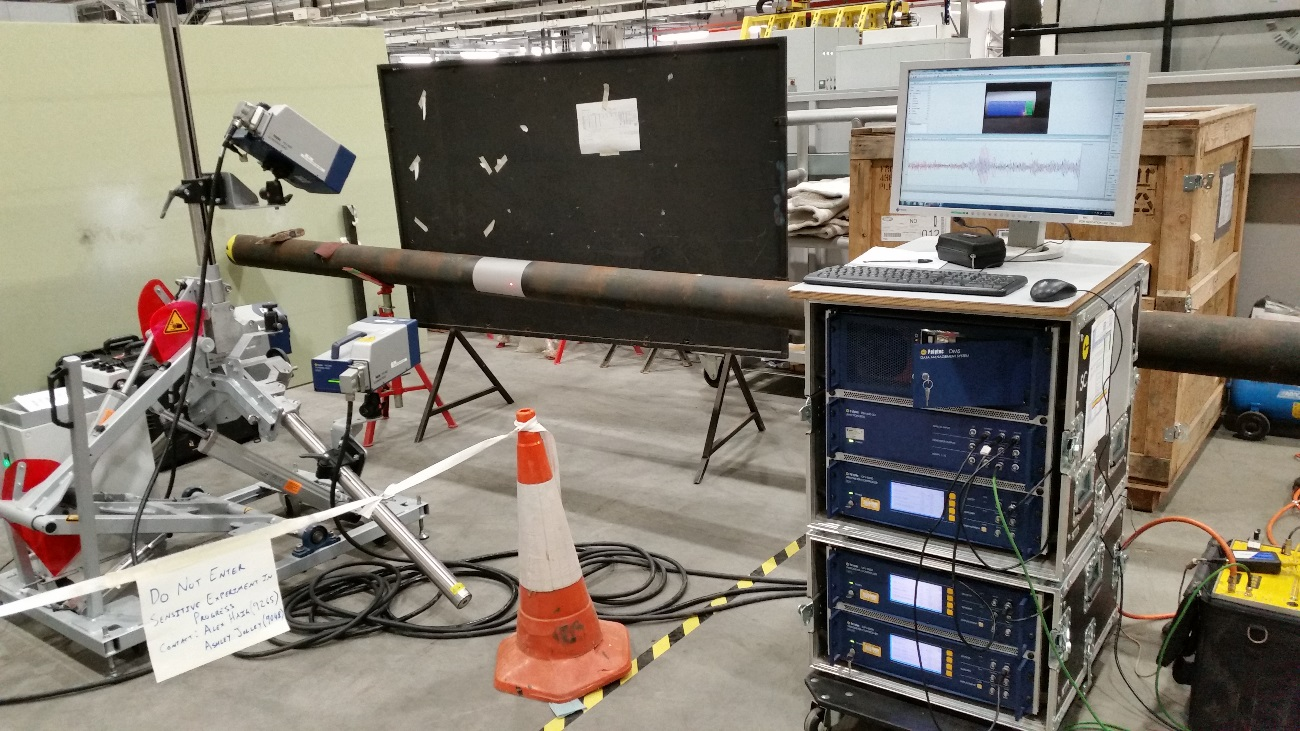
Experimental set-up for laser vibrometer experiments at TWI on a 6 inch diameter steel pipe
Example results from laser vibrometer when the standard active focusing technique was applied to a 6 inch schedule 40 pipe