Subscribe to our newsletter to receive the latest news and events from TWI:

Subscribe >
Skip to content

CoreFlow®: A Sub-Surface Machining Process

CoreFlow® is a highly disruptive, sub-surface machining technique invented at TWI. This solid state process is a development of friction stir welding (FSW) and friction stir channelling (FSC) which allows for sub-surface networks of channels to be integrated into two-dimensional or three-dimensional monolithic parts in a single manufacturing step. These channels can then be used for heat exchange or other applications.

History and Development of CoreFlow®

For over 75 years, our customers have trusted us to deliver Technical Excellence, and TWI has remained at the forefront of solid phase friction welding and processing technology. Active and innovative in welding research and development since the 1960s, TWI has been responsible for many key innovations and developments in solid phase joining. The most notable examples are friction stir welding (FSW), which was invented at TWI in 1991, and the development of linear friction welding (LFW) into a mature joining process for turbine blades.

Friction stir channelling (FSC) is an innovative solid-state process, derived from FSW, for integrating sub-surface networks within metal structural elements. In 2005, the original FSC concept was patented by Rajiv S. Mishra. In his work, poor material consolidation during FSW was deliberately promoted in order to produce a continuous void along the tool path. However, despite its great potential, this technology had not been adopted by industry, mainly by not fulfilling the required repeatability, surface finish or design flexibility.


Coreflow Services Page Fig 1

CoreFlow® tooling description and main process parameters

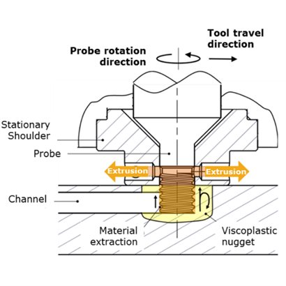
TWI invented and patented a new stationary shoulder variant of FSC (SSFSC) which has proven to overcome many of the drawbacks of conventional FSC. A stationary shoulder is employed to confine the nugget of viscoplastic material, limiting the flow of material extracted by the probe. With the appropriate rotation direction, the geometrical features of the probe cause part of the nugget material to be conveyed into the shoulder. The material extracted is then re-directed towards a series of vents in the shoulder and expelled.

As the tool assembly traverses along a pre-defined path, the process of extracting the material leads to the formation of i) a closed channel within the workpiece and ii) the production of extruded wire. Process parameters and tool designs are combined such that the rate of material extraction per unit distance is limited to maintain a fully consolidated channel ceiling.

The cycle is initiated by plunging the rotating probe into the plate. Once the probe reaches its target plunge depth, the machine initiates its traverse motion. As the tool traverses along the workpiece, the plasticised material is conveyed upwards by the rotating probe threads, into the shoulder and then expelled as extruded material. This subtraction of material leads to the formation of a closed sub-surface channel.

It is interesting to note that the material extruded from the plate in the form of wire could be used as feedstock for other processes, like wire-based additive manufacturing, or could be used simply as welding wire. CoreFlow®, indeed, is capable of extruding an unlimited length of wire from a plate or a pipe.

This process, labelled ForgeWire, is of great interest for producing spool of wire from materials with poor extrudability, such as alloys of aluminium or magnesium. Wire manufacturers or additive manufacturing process developers now have a quick option for producing wire with a tailored chemical composition and from experimental alloy formulations (e.g. Aluminium-Lithium or Aluminium-Scandium), potentially even directly from rolled product or cast billets.

Coreflow Services Page Fig 2

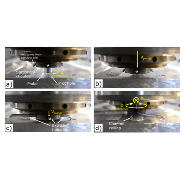
Main stages of the CoreFlow® cycle: (a) Start of probe spindle rotation; (b) Plunge into workpiece; (c) Probe is engaged with the workpiece and shoulder contacts the workpiece surface which initiates material extrusion; (d) Tool traverses along a defined path to form a sub-surface channel with consolidated channel ceiling, extruding material as it travels

Demonstrators and Channel Cross Section

In the last few years, the CoreFlow® concept has been demonstrated and further developed by TWI. AA6082-T6 and AA1050-H14 plates have been successfully processed, with a thickness varying from 5 to 50 mm. Moreover, flat and tubular demonstrators were successfully manufactured, featuring channels along linear, curved and helical trajectories. The demonstrators passed both leaking and pressure testing, with leak rates well below 10-8 mbar∙L/s and pressure up to 9 bar.

The channel cross-section geometry varies from rectangular to triangular, depending on the parameters used. All channels feature a flat bottom surface, with well-defined edges, coincident with the probe outline, as shown in the figure. From the micrograph it is also possible to appreciate how the anisotropic grain orientation in the parent material, caused by the plate sample rolling process, transforms into a fully recrystallized microstructure in the channel ceiling due to the stirring action of the probe in the viscoplastic material.

Press Releases

Find out more about CoreFlow®:

Core Research Programme (CRP) and Joint Industry Projects (JIP)

Core Research

Each year the TWI Core Research Programme (CRP) addresses challenges on behalf of our Industrial Members as well as developing specific technologies and processes. Each of the projects under the CRP is focussed on engineering, materials or manufacturing technologies.

Find out more here

Joint Industry Projects

TWI also conducts Joint Industry Projects (JIPs) that bring together groups of Industrial Members to share the cost of research activities in areas of mutual industrial interest, gaining exclusive access to the outcomes. These projects cover a broad range of topics.

Find out more here

Applications and Use Cases of CoreFlow®

CoreFlow® already looks set to find revolutionary applications in the manufacture of heat exchangers, cooling systems, integrated fluid management and the general light-weighting of structures. Heat exchangers can be found everywhere from cars to aeroplanes, but also communication platforms, satellites and ships.

The trend to increase power densities in the electric and electronic market, is leading to an increased heat generation and driving a collective demand for low cost, compact, lightweight and efficient heat transfer solutions. In electric vehicles (EVs), for example, battery packs, power electronics and electric motors release heat during charging and driving. Similar challenges are also experienced within EV charging station systems. These demands are more and more aggravated by the need of faster-charging rates, improved performance and autonomy and a general ambition to make EVs more affordable and charging networks more convenient. Currently, conventional heatsinks, water blocks, or serpentine pipe heat exchangers are incorporated inside the EV or charging station to prevent excessive temperatures that could lead to decreased performance or battery derating. These systems take up space, add weight and manufacturing complexity to the vehicle, therefore CoreFlow® represents a huge opportunity to solve these challenges by manufacturing battery trays with integral cooling channels built within the metallic structure.

Aerospace is another industry in which thermal management solutions can be implemented using the CoreFlow® process. Aircraft engine cooling, for example, is usually performed by heat exchangers located between the engine and the nacelle, cooling the engine oil using air or fuel. These components, however, disrupt the airflow, creating drag and decreasing thrust output. With CoreFlow® cooling networks could be incorporated directly in the nacelles. The same applies to hydraulic cooling systems, which are usually installed under the wing surface and could be replaced by integrated manifolds manufactured by CoreFlow®, rather than hoses, pipes and fittings.

The channels produced by CoreFlow®, could be used also for anti-icing systems or for embedding instrumentation in metallic surfaces or for reducing the aircraft heat signature.

The technique can also be used to create lubrication networks for hydraulics, to embed instrumentation into a structure, to perform cable management, or simply for additional light-weighting. Outside of transport, CoreFlow® can be used for the cooling of data servers, communication infrastructures and radar installations or to manage the thermal load in manufacturing equipment, for example in the semiconductor or display manufacturing industry.

Currently, FSW is one of the most promising technologies for manufacturing heat exchangers. Their complex geometry currently forces engineers to split production in two stages. Typically, in the first stage, a housing is casted, extruded or machined from a solid block of metal (usually aluminium or copper) which incorporates cooling features and channels to circulate the cooling fluid through the part. In the second stage, a lid is joined and friction welded in order to isolate the cooling channels from the environment and seal the component. FSW has become the most effective choice to perform the second stage of this manufacturing process.

Coreflow-Services-Page-Fig-3-550x550

CoreFlow® overcame these challenges by machining the cooling channels in the part in a single step. Helical serpentines can be successfully incorporated into aluminium piping or housings to create a thermal management functionality. By creating a channel below the surface of a structure, CoreFlow® provides an integrated method to vent heat from a part without having to add extra pipework or other complex and costly solutions.

This translates not only to a simpler process, but also to a more efficient and environmental friendly manufacturing method, using approximately 20% less raw material, producing almost 80% less waste (in form of wire), and therefore weighing less than its conventional counterpart.

TWI is continuing to develop CoreFlow® by defining guidelines for use with different workpiece materials, while working on a range of industrially-relevant technology demonstrators.

With a variety of applications having already been proposed for CoreFlow®, this new friction technique could soon be used in industries ranging from aerospace and automotive to electronics and sensors.

Those wishing to see more technical or commercial information about CoreFlow® can visit our CoreFlow® FAQs page.

For more information on CoreFlow® and how it could help with your applications, please contact the Friction and Forge Processing section at TWI contactus@twi.co.uk.

For more information please email:


contactus@twi.co.uk