Artificial Intelligence for NDT Scanning of Unknown Geometries using Collaborative Robots
TWI Industrial Member Report 1201-2025 [pdf / 1,266KB]
By Mark Sutcliffe and Calum Hoyle
Industrial Need
Robotic inspection for NDT inspection is currently limited to pre-planned paths using fixed robots or in-situ inspection using portable robots, again with a fixed path. In order to combat this and speed up inspection times and remove the requirement for pre-planned robotic paths, a solution is required that allows a probe to be placed on the surface of a component and with no prior knowledge of the component set the system to scan the weld based upon the ultrasonic feedback from a geometry feature within the weld. Having this capability also removes the need for a human operator to be positioned in potentially hazardous conditions while the inspection is being carried out. The only human input from this technique would be the initial probe placement and the identification of the weld geometry to be followed. This would drastically reduce human exposure to hazardous conditions.
Key Findings
- System developed to inspect unknown welded geometries.
- System requires minimal human input.
- System is cobot deployed.
- System maintains constant contact with the surface when scanning.
- System successfully scanned the samples outlined in the report.
- System has some skew ability, however further work is required to improve the skew capability.
Impact
The aims of the project were:
- Develop a prototype system that can automatically scan an unknown welded geometry.
- Develop a prototype system which is cobot deployed, and maintains contact with the surface while the probe traverses the component surface.
- Develop a prototype system to position the probe and adjust offset and skew based on the ultrasonic feedback.
The aims of the project were met, as a system was developed which can scan an unknown weld geometry. The system was also cobot deployed and maintains contact with the surface while the probe traverses the component. The system also updates the probe position and skew based on the ultrasonic feedback. This was proven on an ‘s’ weld, however further work is required on the skew aspect for other scenarios.
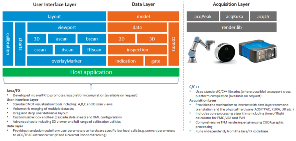
Figure 1 Crystal SDK overview
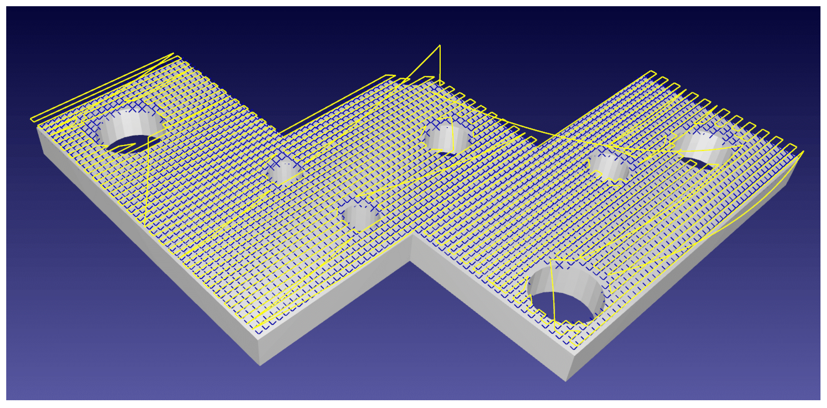
Figure 2 Demonstration of CFSA [1]
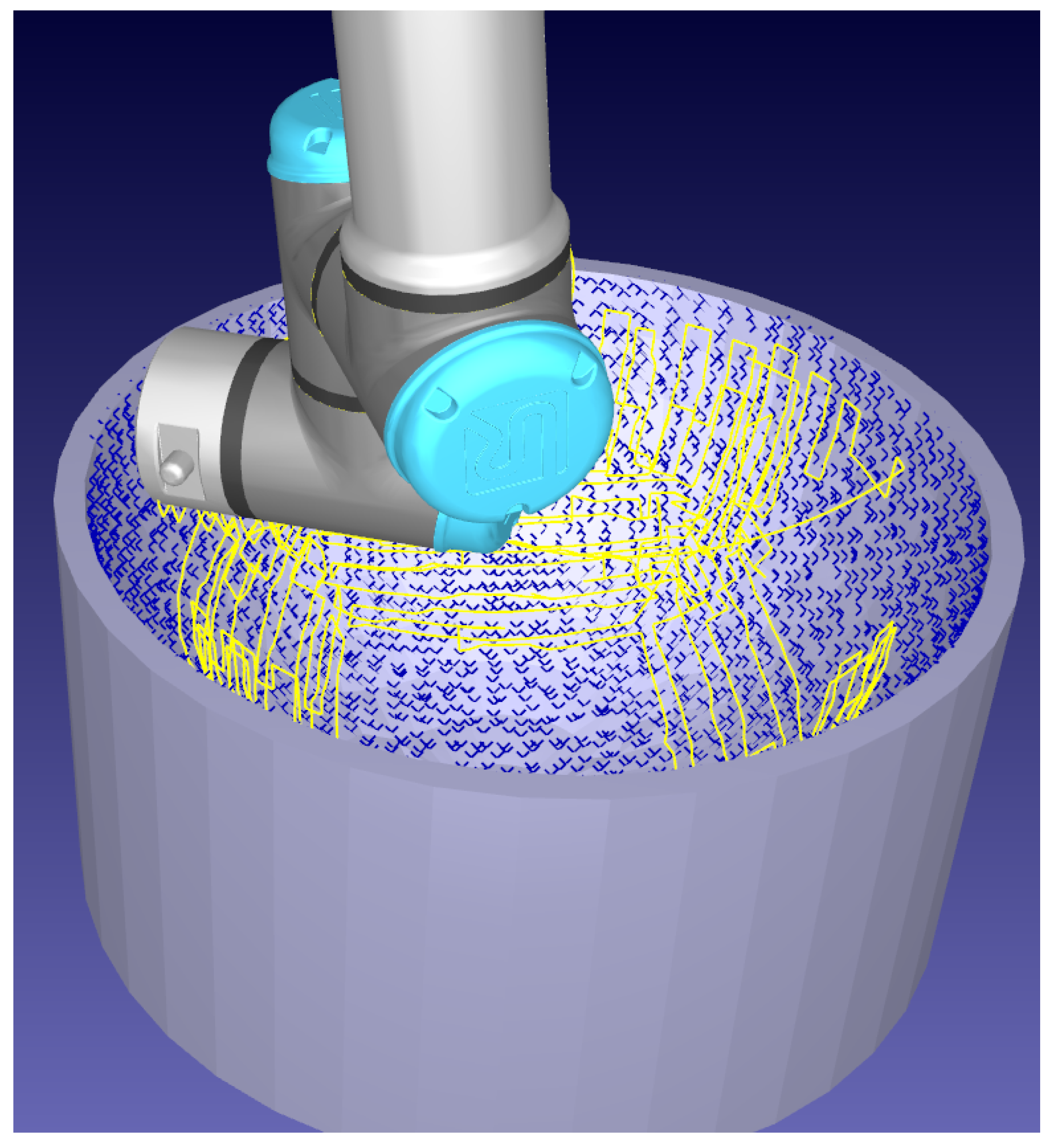
Figure 3 Demonstration of complex curvature with CFSA
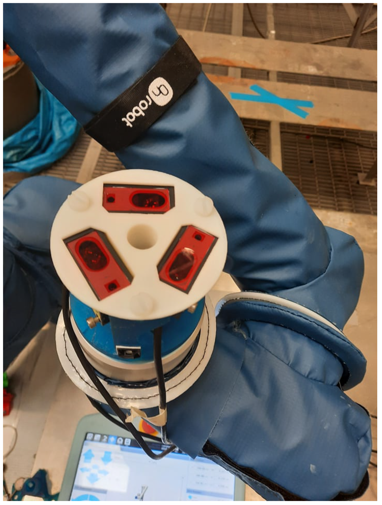
Figure 4 Tri-laser holder, attached to the UR10e flange. The design with rotational symmetry around axis 6 of the robot minimised the footprint of the tool.
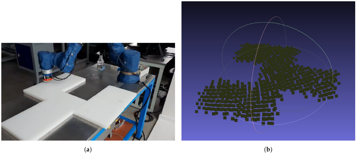
Figure 5 Automatic online profiling and scanning of an object with non-smooth shape
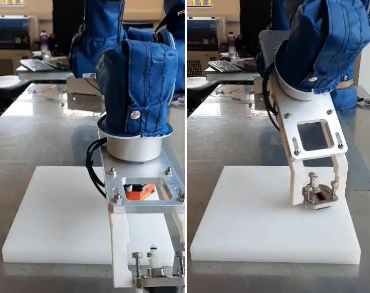
Figure 6 NDT and TRI-Laser configuration
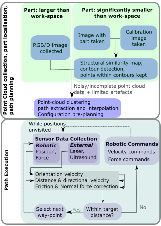
Figure 7 LPAS pipeline
Figure 8 RGB/D Point Cloud Detection
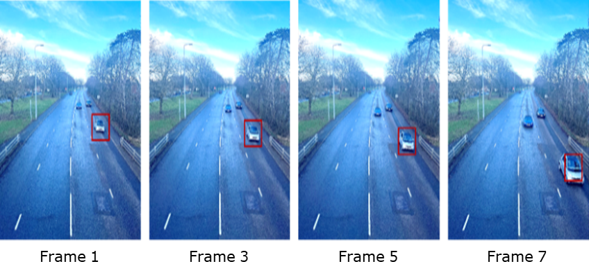
Figure 9 Tracking example by using meanshift algorithm

Figure 10 Meanshift algorithm schematic
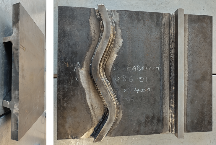
Figure 11 Weld plate with fillet welds
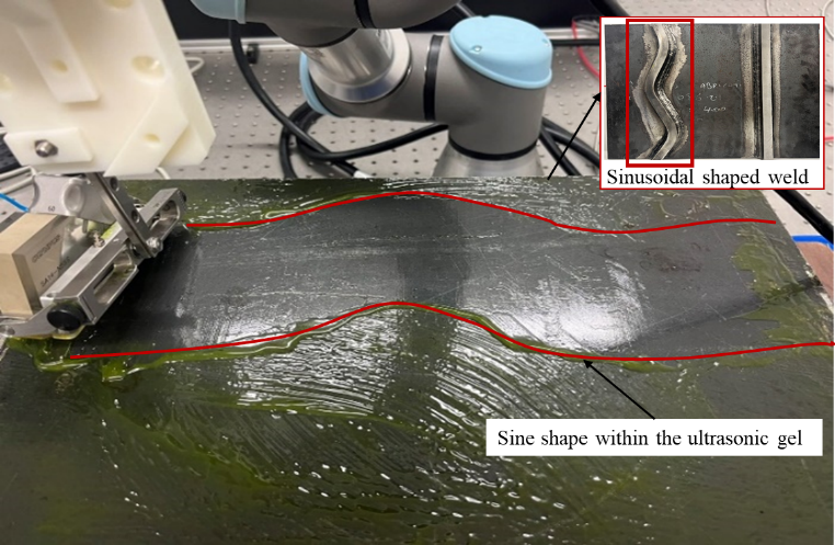
Figure 12 Automatic weld tracking
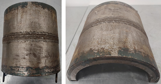
Figure 13 Half-pipe sample
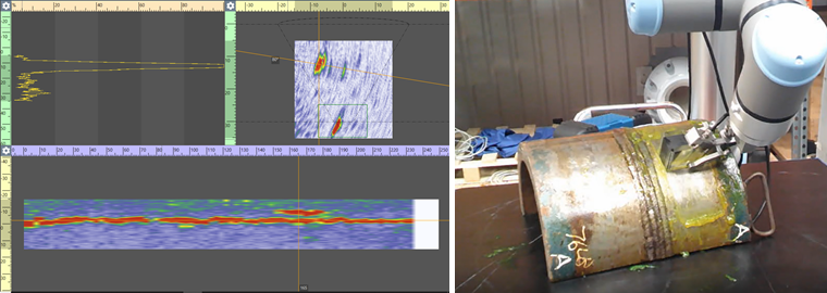
Figure 14 Half-pipe Inspection