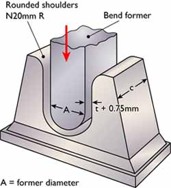
 Fig.1(a) shows a guided bend test jig that uses a male and a female former, the commonest form of equipment
 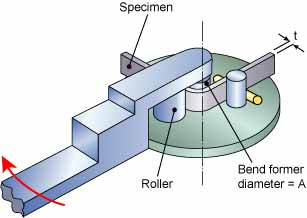 Fig.1(b) shows a wrap-around guided bend test machine that works on the same principles as a plumber's pipe bender
The strain applied to the specimen depends on the diameter of the former around which the coupon is bent and this is related to the thickness of the coupon 't', normally expressed as a multiple of 't' eg 3t, 4t etc.
The former diameter is specified in the test standard and varies with the strength and ductility of the material - the bend former diameter for a low ductility material such as a fully hard aluminium alloy may be as large as 8t. An annealed low carbon steel on the other hand may require a former diameter of only 3t. The angle of bend may be 90°, 120° or 180° depending on the specification requirements.
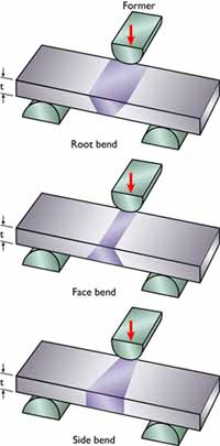 Fig.2 Material over 12mm thick is normally tested using the side bend test that tests the full section thickness
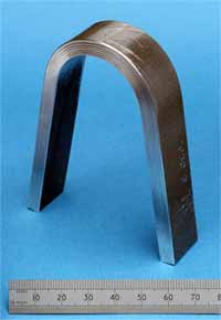
On completion of the test the coupon is examined for defects that may have opened up on the tension face. Most specifications regard a defect over 3mm in length as being cause for rejection.
For butt weld procedure and welder qualification testing the bend coupons may be oriented transverse or parallel to the welding direction.
Below approximately 12mm material thickness transverse specimens are usually tested with the root or face of the weld in tension. Material over 12mm thick is normally tested using the side bend test that tests the full section thickness, Fig.2.
Where the material thickness is too great to permit the full section to be bent the specifications allow a number of narrower specimens to be taken provided that the full material thickness is tested. Conventionally, most welding specifications require two root and two face bend coupons or four side bends to be taken from each butt welded test piece.
The transverse face bend specimen will reveal any defects on the face such as excessive undercut or lack of sidewall fusion close to the cap. The transverse root bend is also excellent at revealing lack of root fusion or penetration. The transverse side bend tests the full weld thickness and is particularly good at revealing lack of side-wall fusion and lack of root fusion in double-V butt joints. This specimen orientation is also useful for testing weld cladding where any brittle regions close to the fusion line are readily revealed.
Longitudinal bend specimens are machined to include the full weld width, both HAZs and a portion of each parent metal. They may be bent with the face, root or side in tension and are used where there is a difference in mechanical strength between the two parent metals or the parent metal and the weld. The test will readily reveal any transverse defects but it is less good at revealing longitudinally oriented defects such as lack of fusion or penetration.
Whilst the bend test is simple and straightforward to perform there are some features that may result in the test being invalid.
In cutting the coupon from the test weld the effects of the cutting must not be allowed to affect the result. Thus it is necessary to remove any HAZ from flame cutting or work hardened metal if the sample is sheared.
It is normal to machine or grind flat the face and root of a weld bend test coupon to reduce the stress raising effect that these would have. Sharp corners can cause premature failure and should be rounded off to a maximum radius of 3mm.
The edges of transverse bend coupons from small diameter tubes will experience very high tensile stresses when the ID is in tension and this can result in tearing at the specimen edges.
Weld joints with non-uniform properties such as dissimilar metal joints or where the weld and parent metal strengths are substantially different can result in 'peaking' of the bend coupon. This is when most of the deformation takes place in the weaker of the two materials which therefore experiences excessive localised deformation that may result in premature failure.
A dissimilar metal joint where one of the parent metals is very high strength is a good example of where this may occur and similar peaking can be seen in fully hard welded aluminium alloy joints.
In these instances the roller bend test illustrated in Fig.1(b) is the best method of performing a bend test as each component of the coupon is strained by a similar amount and peaking is to a great extent eliminated.
Related Specifications
|
BS EN ISO 5173
|
Destructive Tests on Welds in Metallic Materials - Bend Tests
|
|
ASME IX
|
Welding and Brazing Qualifications
|
|
ASTM E190-92
|
Guided bend Test for Ductility of Welds
|
This article was written by Gene Mathers.
This Job Knowledge article was originally published in Connect, November 2004. It has been updated (figure 1b) so the web page no longer reflects exactly the printed version.