Allan Sanderson
Paper presented at IIW ASSEMBLY Quebec, Canada, August 2006, IIW Doc. IV-913-06
Abstract
EBW equipment was first installed at TWI in the early 1960s. Although of limited performance, the deep narrow, single pass welds made in 12mm steel created a great deal of excitement and spawned an extensive, higher power, research and development programme. This led, by the early 1970s, to an advanced, high vacuum, 75kW, 150kV machine capable of 300mm penetration in steel, 450mm in aluminium alloy and 125mm in copper alloy. The work set the trend for subsequent decades and notable further developments took place in both electron gun and power source design to meet the demands of industrial thick section applications.
Electron sources were improved to achieve longer cathode life, even higher performance and greater beam stability. Flashless, intelligent, switch mode inverters replaced conventional power sources. Differentially pumped systems were devised to permit operation at pressures up to several millibar to offset the limitations of vacuum operation and both external and internal chamber guns were designed for a wide range of large applications.
Significant advances were also made in Non-Vacuum EBW, with the establishment of a large 300kV, 150kW facility and in recent times a special high frequency beam pulsing device was used to increase the penetration depth and reduce the width of welds made at atmospheric pressure.
In addition, special high intensity guns were designed for material surface processing. These are capable of producing innumerable macro and micro effects, offering a whole new range of possibilities for metal bonding for aerospace, automobile and medical applications.
EBW equipment and application highlights are described with particular emphasis on work carried out in the last few years.
1. The early years
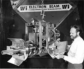
Fig.1. EB machine established at BWRA in 1963
When electron beam welding equipment was introduced at TWI (then BWRA) in the early 1960s it was very much viewed as a laboratory curiosity. Certainly, the equipment by modern standards was quite crude, Fig.1. Remarkably it did produce some exciting results; compared with all other contemporary welding processes, the high depth-to-width ratio welds were indeed unique. Interestingly, the welds made with this 30kV, 9kW unittended to exhibit quite rounded fusion zone tips, thus avoiding the root defects characteristic of many later high voltage machines. On the other hand, the low accelerating voltage of this early equipment limited its maximum penetration capability and working distance range. Also beam distortion, instability and power supply ripple problems were of great concern. [1]
As with all new processes introduced at TWI, the approach has been to study performance, understand the electrical and physical properties of the equipment and then try to use the knowledge gained to extend the performance. The physics of the electron beam generation, focusing and control systems were therefore studied in depth and out of this work emerged a plan to build a 150kV, 75kW system.
2. The 150kV, 75kW high vacuum development
This was considered to be a very ambitious project, but by the early 1970s a good deal of success had been achieved. Special finite difference software was written in order to analyse electron flow and high voltage stress levels in the gun enclosure. The pioneering work undertaken paid off and resulted in one of the world's first truly high power machines, Fig.2. The electron gun, powered by a 400-cycle motor generator set, was a directly heated triode and employed a 2.5 x 2.5 mm2 tungsten ribbon filament.
Fig.2. 150kV, 75kW EB gun column mounted on 6m 3 chamber
Penetration depth in steel was rapidly extended from a few millimetres, to 100mm, then 150mm, 200mm and finally, 300mm. Extremely deep test melt runs were also made in copper and aluminium alloys, Fig.3a and b. Fig.3b was certainly the deepest melt run ever made in aluminium alloy in the 1970s and possibly is still unsurpassed. These successes led to equipment being built for Japan and a licence agreement followed, under which some 10 machines of this type were introduced into the Japanese fabrication sector of the power industry.
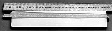
a) 125mm copper-chromium alloy
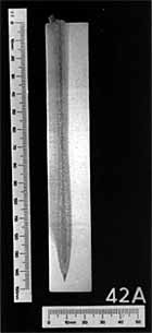
b) 590mm 5083 aluminium alloy
Fig.3. High depth-to-width ratio melt runs made in high conductivity materials a) 125mm copper-chromium alloy b) 590mm 5083 aluminium alloy
Numerous studies were launched at TWI and elsewhere to explore the weldability, metallurgy and mechanical properties of a wide range of ferrous and non-ferrous materials. Not surprisingly, early attempts to make sound, tough welds particularly in very thick section ferritic steels resulted in a whole new range of flaw types to be categorised and studied. Considerable effort was then required to understand and prepare solutions to these problems. Similarly, the dramatic increase in beam power from a few kilowatts to 75kW identified all manner of equipment weaknesses. The intense high power electron beam produced copious volumes of metal vapour streaming with line of sight into the electron gun. This frequently causes gun electrode flashover and rapid deterioration of the directly heated tungsten ribbon filament used at that time. A vapour filter device, known as a magnetic trap device, was developed which deflected the electron beam around a central plug blocking the line of sight and great improvements were achieved with much reduced flash-overs and extended filament life. [2,3]
Long-term beam stability, however, became a significant factor in the pursuit of a reliable, rugged industrial machine design. It was realised that even with the magnetic trap device, thermal distortion of the ribbon filament had an unacceptable effect on beam focus position, power density and hence weld fusion zone shape and penetration depth.
3. Indirectly heated gun developments
As a consequence it was decided to develop a gun design with an indirectly heated slug cathode. In the first instance, refractory metals such as tantalum or tungsten were employed and the gun configuration demanded three auxiliary supplies, namely primary filament, grid voltage supply for beam control and an additional indirectly heated cathode supply. This approach was pursued over a number of years, but it became evident that the complexity of gun power supplies, multi-core cables and high voltage gun and tank terminations were leading to increased equipment component failures.
It was also realised that the use of a grid electrode providing fast beam current control, was a source of weakness. Momentary breakdown of the grid supply in the gun caused by the influx of even small amounts of metal vapour could lead to sudden surges of beam power causing severe damage to the component being welded. Interest, therefore, grew in the use of diode guns where beam current was controlled by cathode temperature. [4]
The first industrial package version of an indirectly heated diode gun column is shown in Fig.4. This was supplied to the Framatome Research Laboratories at Le Creusot in France. It was used for thick section nuclear reactor component welding studies. Unlike the earlier TWI equipment, it incorporated a switch mode inverter running at 5kHz; this provided the primary power. [4] The inverter contained flashless control circuitry, whereby any prolonged gun discharge effects would invoke momentary shutdown of the power source to quench the discharge. The power was then rapidly restored avoiding undue disturbance of the welding process. Other special features were the visual optics, allowing real-time viewing of the welding process, even at very high power levels and also a real-time seam tracking system making use of a hidden collector-detector, [5] Fig.4 & 5. This device avoided seam tracking signal interference caused by the strong positive ion flux emitted by the weldpool. Similar units have been used for real-time electron imaging at high power levels. In both cases the full welding beam was deflected ahead of the weld necessitating very high-speed deflection to avoid melting of the joint line feature. The diode gun was capable of 300mm penetration of steel in a single pass, Fig.4b and welding very close to the edge of a steel block without breaking through the sidewall. Incredibly this was achieved in the flat position mode, only 8mm from the sidewall, Fig.4c. This welding procedure was developed for 'band to block to blade' welding for steam-turbine diaphragms.
| a) gun column |
b) 288mm low alloy steel |
 |
 |
 |
c) 145mm deep fusion zone, 8mm from sidewall of steel block |
| Fig.4. Indirectly heated diode (150kV, 100kW) gun supplied to Framatome in 1990 |
Fig.5. Example of thick section steel curvilinear test specimen successfully seam tracked using a hidden collector-detector
4. Non-vacuum developments
In the 1970s and 1980s several small scale projects were undertaken to establish high power Non-Vacuum beam equipment at TWI. Some interesting fusion zone profiles were produced in steel up to some 40mm thick, but it was not until the late 1980s that sufficient industrial interest had been generated to launch into the construction of a large scale 300kV, 150 kW Non-Vacuum facility, Fig.6a and b.
a) the X-radiation shield
b) schematic illustrating potential use of Cartesian robot gantry for NVEB
Fig.6. Large scale 300kV, 150kW Non-vacuum facility
In view of the difficulties that had been experienced with failure of auxiliary supplies for high vacuum equipment, even at the 150kV level, it was decided to pursue a novel technology, which had been explored in the 1970s. This early work had shown that a radio frequency (RF) isolation transformer, locally coupled at the gun column [6, 7, and 8] could generate auxiliary power supplies.
The approach was very successful; it proved possible to heat a primary filament together with an indirectly heated diode cathode with a total RF power input of approximately 200 watts. The coupling frequency chosen for the prototype was 49MHz.
The gun column ( Fig.7a) consisted of three differentially pumped stages plus an over-pressure stage into which helium was fed to reduce beam scattering at atmospheric pressure. Fig.7b shows a graph indicating the penetration levels achieved in 2¼ Cr Mo steel and pure copper with this equipment. The accelerating voltage employed in this case was 200kV and the welds were made in the flat position. Subsequently the equipment was operated at voltages in the 250 to 270kV range to reduce electron scattering effects and improve beam penetration.
b) beam penetration achieved in low alloy steel and copper at 200kV
Fig.7. 300kV, 150kW Non-vacuum
As in the case of high vacuum EBW, it was found that penetration performance was significantly increased in the horizontal-vertical (HV) mode. Fig.8 shows a typical weld made in 30mm stainless in the HV welding mode. Although the fusion zone profile was by no means ideal, it did demonstrate that NVEB was capable of producing high depth-to-width ratio welds.
Fig.8. NVEB weld made in 30mm, 316 stainless steel in the HV mode; beam power 250kV x 300mA; welding speed 1350mm/min
5. Reduced pressure EBW
5.1 Research
Many of the potential thick section, industrial applications in the 1990s required in excess of 50mm penetration and it was felt that these could best be undertaken in an intermediate pressure regime. Of course, it was relatively easy to fire a NVEB beam into a chamber in which the pressure and gas species could be readily controlled. Studies were made of the beam profiles at pressures of between 1000mbar and less than 0.1mbar and it was discovered that with suitable electron optics, a near parallel electron beam could be sustained over a long working distance range even at pressures of the order 1mbar, Fig.9a. Indeed the welds made with this type of beam had excellent profiles. Moreover, single pass penetrations of up to 150mm proved very easy to make, Fig.9b.
a) 200kV 60kW beam in helium at 5mbar
b) 150mm thick C-Mn steel penetration at 1mbar; 200kV, 300mA, 100mm/min
Fig.9. Reduced pressure operation a) 200kV 60kW beam in helium at 5mbar b) 150mm thick C-Mn steel penetration at 1mbar; 200kV, 300mA, 100mm/min
5.2 Nuclear waste burial programmes
5.2.1 Copper canister welding
In the 1980s and 1990s the Swedish Nuclear Fuel and Waste Management Company (SKB) had been working very closely with TWI on the fabrication and EB sealing of thick section copper canisters for high level nuclear waste burial. The nominal canister dimensions were 1m diameter by 5m in length with a wall thickness of 50-60mm. Although it had been proved that high vacuum (5x10 -3 mbar) equipment was fully capable of achieving this level of penetration depth in a single pass, up until the early 1990s, the occurrence of defects at the tip of the fusion zone, (so called root defects) were found to be difficult to eliminate.
On the other hand, NVEB invariably produced weld fusion zones with a rounded tip, probably because of the diffuse nature of the beam compared with that of a beam focused in a high vacuum environment. Similarly, beams applied at pressure levels of the order of 1mbar could produce round bottomed fusion zones free from root defects. [9] In the case of copper canister lid sealing, there was also concern that the large surface area of the canister would represent a large outgassing load. Also the inner receptacle, enclosing the high level nuclear waste, would bein close contact with the copper canister possibly trapping gas. Potentially, this could produce serious welding process instabilities if high vacuum (EBW) were employed. In contrast, Reduced Pressure EBW is relatively immune to pressure fluctuations because the electron gun is isolated from the welding environment by the differentially pumped gun column cavity structure separated by fine bore nozzles.
Fig.10 shows the gun column designed and manufactured for SKB in 1996, and Fig.11, a typical weld cross section and lid weld. The gun column again employs a locally coupled RF transformer providing filament heating and back-bombardment power to the diode gun cathode. The equipment is rated at 200kVand 100kW and routinely welds at 190kV at a beam current level of typically 340-420mA.
Fig.10b) column schematic showing internal structure
Fig.10. 100kW, 200kV Reduced pressure equipment designed and manufactured for SKB in 1996
a) fusion zone exhibiting well radiused tip free from root defects
Fig.11. Typical copper canister lid weld showing
5.2.2 Nickel alloy canister welding
Reduced Pressure EBW is also being pursued by the USA for the sealing of NiCrMo alloy (Alloy 22) canisters for high level nuclear waste burial. Orbital welding is required so that the canisters do not have to be rotated or significantly manipulated. Insensitivity to small pressure fluctuations favours the use of an orbiting welding head involving large sliding seals and allows the required pressure to be attained quickly by means of mechanical pumps. The ability to operate under remote hot-cell conditions in a relatively coarse vacuum in this way is considered very attractive. Regarding, the welding process itself, high quality welds with near parallel fusion zones have been produced in the 33mm thick Alloy 22 material, Fig.12a. The welding time for RPEB is some 9 minutes compared with 250 minutes for GTAW Fig.12b.
a) Reduced pressure EB fusion zone
Fig.12. Comparison of weld profiles in 33mm thick NiCrMo alloy (Alloy 22) as proposed for Yucca Mountain nuclear waste package corrosion barrier a) Reduced pressure EB fusion zone b) GTAW fusion zone
The RPEB fusion zone produces far less distortion and residual stress than GTAW welding. Distortion must be kept to a minimum to permit assembly of the complex canister elements and residual stress is of concern because of its adverse effect on the corrosion resistance of the alloy. [10]
Other potential Reduced Pressure applications include the fabrication of large-scale thick section tubular components. Again the ability to operate with relatively crude local seals, yet maintaining an outstanding welding rate would be of great benefit, for example, in the fabrication of offshore wind tower monopiles. [11]
6. Pulsed non-vacuum EBW
Welding rates for NVEB are potentially very high and for thick section material the process offers several advantages over and above the newer processes such as laser welding, friction stir and Reduced Pressure EBW. The ability to tolerate joint gaps and edge mismatch whilst achieving well-rounded weld beads makes it ideally suited for fabrication of road vehicle structural components. [12]
At operating pressures of even several tens of millibar an electron beam undergoes minimal scattering, but as the pressure approaches one atmosphere substantial electron-atom collisions occur. For a conventional NVEB equipment,operating at say 175kV, the useful working range for welding is only some 5 to 20mm. The degree of scattering can be reduced and working distance range extended by employing higher accelerating voltages, hence the 300kV development described above. However, this increases the size, weight and bulk of the equipment making it less favourable for mounting the gun, for example, on a Cartesian robot, Fig.6b.
One new approach that promises to substantially increase penetration performance of NVEB is the use of pulsed beams. As in the case of high vacuum EBW, it has been found that penetration range can be increased for a given average power level by using high peak power levels. In a recent TWI research programme, it has been shown that penetration depth in steel can be increased by 50% combined with a corresponding reduction in weld width, particularly in the vicinity of the top bead. Pulsing also appears to alter the solidification mechanism that often leads to solidification cracks in deep NVEB welds in ferritic steel, Fig.13.
Fig.14 shows a melt run made in the flat position in low alloy steel using a pulsed beam. It will be noted that the fusion zone is almost parallel sided with a well-rounded tip. Apart from minor pores the fusion zone was sound. The run was made at an average power of 26.3kW at a welding speed of 480mm/min. The equipment developed at TWI to study pulsed NVEB welding, consists of an RF excited diode gun but with the addition of a high frequency grid electrode. As in the case of the indirectly heated diode guns, the grid supply makes use of a locally coupled RF supply that is modulated to achieve a square-wave alternating voltage in the gun cartridge. The AC voltage is rectified by means of a thermionic diode making use of the main cathode. [6] The grid supply allows square-wave pulsing up to frequencies of 5kHz. Fig.15 shows a general view of the gun column set up for welding. [13]
Fig.13. Non-pulsed NVEB melt run in ferritic steel made in flat position showing a centreline crack and very wide top bead
Fig.14. 22mm deep melt run made in the flat position in low alloy steel with a pulsed NVEB beam
Fig.15. Non-vacuum EBW equipment with high frequency pulsing facility
7. In-chamber reduced pressure gun column
For EBW employing a vacuum chamber, it has long been recognised that for a given chamber length, the maximum weld length is best achieved with a gun column mounted inside the chamber on a long traverse. Since the early 1990s TWI has operated a compact in-chamber gun within a 150m 3 chamber. This has been successfully used for all manner of large-scale welding operations. In this mode the chamber was pumped by mechanical pumps backing two large oil diffusion pumps, Fig.16.
To achieve an operating pressure of 5 x10 -3 mbar, typically took a large proportion of 1 hour, the exact time being very much dependent on the time period the chamber was left open for loading operations and the prevailing humidity of the air. Some significant reduction in pump-down time was achieved by the use of a cryo-pump which effectively removes the moisture content of the residual air during pump-down. Nevertheless, the growing interest in Reduced Pressure welding and the need to demonstrate its performance on large-scale components necessitated the conversion of the gun column to a differentially pumped system. This was mainly carried out in 2005 and the system was re-commissioned at the beginning of 2006. The control system was also upgraded and substantial fume extraction and vacuum chamber cleaning equipment was installed. Fig.17 shows the Reduced Pressure gun column mounted on a 1.2m Z-traverse supported by a 6m long X-traverse within the chamber.
Fig.17. In-chamber differentially pumped Reduced Pressure gun column in 150m 3 chamber
The three turbo-molecular pumps used to evacuate the column cavities are backed directly by the vacuum chamber. The gun column, unlike other Reduced Pressure gun columns, contains a high quality optical viewing system, allowing real-time viewing of the welding process. The illumination is provided by a focused quartz-iodine bulb projected adjacent to the beam axis and the image is returned on the opposite side of the axis to an on-board CCTV camera. Both the alignment of the visual optics and focus are controlled by a servo-mechanism, enabling sharp focus to be maintained and maximum light to be brought to bear on the workpiece over a wide range of working distances.
The chamber traverse also provides, additional X movement, thus further extending the overall weld length possible. A Y chamber traverse allows the working distance to be adjusted or programmed and various rotary tables can be put onto the chamber on top of the Y-traverse for cylindrical or planetary welding. The gun column can also be set at any angle between horizontal-vertical and flat position, Fig.17.
8. High intensity beams
8.1 Beams deflection development
Historically, the EB Section at TWI has concentrated its main effort on the development of high-power, high-voltage equipment and corresponding thick-section weldability and weld procedural development work. However, the section has always had a low-power capability, mainly served by a 150kV, 6kW machine but more recently augmented by a second upgraded unit. Both the high and low-power machines use electromagnetic deflection equipment for material processing, seam tracking and beam probing. High frequency digital deflection has also been used for many years for creation of various heat patterns in which the welding beam can be split into numerous beamlets allowing selected area heating to be applied to the workpiece for heat-treatment of materials and also for thermal-cycle management to avoid cracking in crack-sensitive materials.
8.2 Surface modification
An offshoot of this work has been the use of high-speed electromagnetic deflection to produce textured surfaces on both metals and on non-metals. Such textured surfaces can contain re-entrant holes and protrusions, which are of great interest for metal to non-metal bonding. The texture is created by local melting and vapourisation; the vapour expels material from the hole formed, with the displaced material forming a ridge around the hole. Fig.18. Such a finish increases the surface area and greatly enhances the adhesion for example, of PVD (physical vapour deposited) and thermal spray coatings.
Surfi-Sculpt TM is an extension of surface texturing and is a new and revolutionary materials processing technology [14,15] that enables controlled surface features to be developed on a range of substrates, predominantly metal but with scope also for polymers and ceramics. Surfi-Sculpt TM features are developed by utilising a series of electromagnetic coils to first focus the beam, then to deflect the beam around the material surface in a rapid and controlled manner at selected points on the surface. At each point a molten pool is formed, and the beam is then translated sideways which leads to material being moved from within the hole to regions around the hole as a result of vapour pressure and surface tension effects. By repeating this process at many local sites, protrusions of several millimetres height are formed, each of which is accompanied by one or more corresponding intrusions or holes, see Fig.19.
Fig.18. Electron beam textured surface
Fig.19. Electron beam Surfi-Sculpt TM surface
Unique patterns can be developed by the controlled manipulation of the beam; the variety of features possible appears almost limitless, Fig.20 and 21. [14]
Fig.20. Networked Surfi-Sculpt TM features
Fig.21. Slanting cones grown from titanium alloy surface a) b)
The process was developed out of a belief that engineering of surfaces is important for many future applications, plus the challenge to stretch electron beam technology for future, unknown needs. To date, the process is finding (or being considered for) applications as diverse as:
- Enhancing joining of dissimilar materials for hybrid structures, for example joining polymer composites to metals (e.g. Comeld technology)
- Improving the adhesion of thermally sprayed coatings to metals
- Controlling liquid or gas flow around a surface
- Processing of pre-coated surfaces to provide local variations in surface properties
- Sculpting of shape memory alloys
- Biomedical implants, wind-turbine blades and jewellery
Surfi-Scuplt TM finishes have, until recently, only been produced at a macro level, where the features are typically of the order of millimetres. There is growing interest, however, in the semi-conductor field and particularly in the medical field, where finer scale structures are required to promote bone cell or cell growth onto metal or non-metallic body implants. This has stimulated further development aimed at producing higher intensity beams at lower accelerating voltage e.g. 30 to 60kV. The use of lower accelerating voltage is required to avoid excessive penetration and spreading of the electron beam in the solid material. Fig.22 shows the special high intensity equipment built up as a test bed for this activity and Fig.23 an early example of a fine Surfi-Sculpt TM surface.
Fig.22. 150kV, 8kW high intensity EB machine
Fig.23. Stainless steel pinnacle array produced by 10Hz, 1000 point 16 line raster at 150kV x 2mA
The electron gun is again an RF excited diode with specially designed electron optics to produce higher beam intensity. The unit is fitted with visual optics providing screen viewing of up to x40 magnification. Work is also in hand to generate back-scattered electron images to study process effects at much higher magnification.
9. Concluding remarks
Electron beam welding was invented over 50 years ago and TWI's R & D involvement in this field spans over 40 years. Therefore, by many, it may be considered a mature process and indeed for routine metal to metal joining this is true. However, not only have significant strides been made in the last four decades, but also by implication many more advances are likely before EB technology can be said to be complete. Advances in electron gun design and methods of generating, controlling and manipulating electron beams will no doubt continue as will the means of applying electron beams to an ever expanding range of material types and a widening spectrum of component complexity.
High vacuum EBW is expected to retain its appeal for welding of oxygen avid materials especially where ultimate precision and cleanliness is required. In contrast, where large scale thick section component welding is required, Reduced Pressure and NVEB processes are expected to gain in popularity. Reduced Pressure EB welding produces comparable results to high vacuum EBW and even at 1 mbar pressure can weld materials in excess of 150mm thick at working distances of several hundred millimetres.
Non-Vacuum EBW is unlikely to have the same working distance range, but single pass penetration is expected to increase towards 75mm in steel and greater in aluminium alloys in the near future. Certainly the ability to weld without the encumbrance of a vacuum chamber will in the case of very large structures, be seen as a great advantage. The application of NVEB is also expected to become more attractive for high speed welding of thin to medium-section materials,where welding speeds in excess of 10m/min are readily possible whilst coping with joint gap and edge mismatch.
Surface engineering for medical, aerospace, semi-conductor and automotive applications are, on the other hand, stimulating further advances in the use of high intensity, low-voltage, low-power beam devices making use of the extremely high brightness possible with electron beams.
10. References
- Sanderson, A. and Adams M.J, 'Beam Characteristics of a 30kV Electron Gun', BWRA report P/27/68, March 1968.
- Sanderson, A. and Livsey, N.B, 'Magnetic Trap Devices for EB Welding', The Welding Institute Res.Bul, 186/4/80.
- Sanderson, A., British Patent No. 1485367 and USA Patent No. 4072356.
- Sanderson, A., and Walker, P. 'Recent Innovations in High Power Electron Beam Equipment designs for Industrial Welding Applications', Proc. of Int. Power Beam Technology Conference, Brighton, UK 10 -12 September 1986 pp 44-1 to pp 44-20.
- Sanderson, A. and Ribton, C .N. 'European Patent application No. 87302431.9'
- Sanderson, A., 'Electron Beam Generators' British Patent 1494077, filed 15 November 1973.
- Sanderson, A. 'Charged Particle Generation' International Patent Spec. 19 November 1993. European Patent EP0627 121.
- Sanderson, A. 'The development of RF Excited Guns for High Power Electron Beam Welding', IIW Doc.No. IV-709-98.
- K.R. Nightingale, Sanderson A., Punshon C.S., L.O. Werme, 'Advances in EB Technology for the Fabrication and Sealing of Large Scale Copper Canisters for High Level Nuclear Waste Burial', Proceedings of 6th International Conference on Welding and Melting by Electron and Laser Beams, Toulon, France (June 1998) vol.1 pp 323-330.
- Wong et al 'Reduced Pressure Electron Beam Welding Evaluation Activities on a Ni-Cr-Mo Alloy for Nuclear Waste Packages' Proceedings of ANS/ENS 2003 Global conference, New Orleans, November 2003.
- Ribton, C.N. and Punshon, C.S., 'Reduced Pressure EB Welding in Power Generation Industry, Proc. Int. Forum on Welding Technology in Energy Engineering September 21 - 23, 2005, Shanghai.
- Dilthey, U, Masny, H and Woeste, K., 'Non Vacuum Electron Beam Technology and Applications', Electron Beam Technology and Applications Conference , SEBTA 2005, September 28-30, 2005.
- Sanderson, A., 2005 'High Power Non-Vacuum EB Welding' TWI Bulletin, May - June 2005
- Dance, B.G.I. 2002 'Modulated Surface Modification' International Patent Publication No. WO 2002/094497 A3
- Dance, B.G.I and Kellar, E.J.C., 2004 'Workpiece Structure Modification' International Patent Publication No. WO 2004/028731 A1
- Buxton, A.L. and Dance, B.G.I., 'Surfi-Sculpt TM - Revolutionary Surface Processing with an Electron Beam' Paper presented at ISEC 2005
Acknowledgements
Acknowledgements are due to DoE of the USA for permission to publish work on the nuclear waste canister associated with the Yucca Mountain project. Thanks are due also to the Industrial Members of TWI and in particular to SKB fortheir support over the last two decades.
The author also wishes to acknowledge the support and substantial contributions made by TWI EB Section staff and colleagues in pursuit of equipment and process advances over the last 40 years.