Eddy current testing is a non-destructive testing (NDT) inspection method used for a variety of purposes, including for flaw detection, material and coating thickness measurements, material identification and establishing the heat treatment condition of certain materials.
Contents

Eddy current testing is one of several non-destructive testing methods that uses the electromagnetism principle for flaw detection in conductive materials. A specially designed coil energised with an alternating-current is placed in proximity to the test surface, generating a changing magnetic field that interacts with the test-part and produces eddy currents in the vicinity.
Variations in the changing phases and magnitude of these eddy currents are then monitored through the use of a receiver-coil or by measuring changes to the alternate current flowing in the primary excitation-coil.
The electrical conductivity variations, the magnetic permeability of the test-part, or the presence of any discontinuities, will cause a change in the eddy current and a corresponding change in the phase and amplitude of the measured current. The changes are shown on a screen and are interpreted to identify defects.
Eddy currents are also known as Foucault currents after French physicist Leon Foucault, who developed a device that demonstrated that eddy currents are created when a material travels within an applied magnetic field. Professor Friedrich Forster customized eddy current technology for industrial applications in 1933, but all eddy current array technologies follow the same principle.
The process relies upon a material characteristic known as electromagnetic induction. When an alternating current is passed through a conductor – a copper coil for example – an alternating magnetic field is developed around the coil and the field expands and contracts as the alternating current rises and falls. If the coil is then brought close to another electrical conductor, the fluctuating magnetic field surrounding the coil permeates the material and, by Lenz’s Law, induces an eddy current to flow in the conductor. This eddy current, in turn, develops its own magnetic field. This ‘secondary’ magnetic field opposes the ‘primary’ magnetic field and thus affects the current and voltage flowing in the coil.
Any changes in the conductivity of the material being examined, such as near-surface defects or differences in thickness, will affect the magnitude of the eddy current. This change is detected using either the primary coil or the secondary detector coil, forming the basis of the eddy current testing inspection technique.
Permeability is the ease in which a material can be magnetised. The greater the permeability the smaller the depth of penetration. Non-magnetic metals such as austenitic stainless steels, aluminium and copper have very low permeability, whereas ferritic steels have a magnetic permeability several hundred times greater.
Eddy current density is higher, and defect sensitivity is greatest, at the surface and this decreases with depth. The rate of the decrease depends on the “conductivity” and “permeability” of the metal. The conductivity of the material affects the depth of penetration. There is a greater flow of eddy current at the surface in high conductivity metals and a decrease in penetration in metals such as copper and aluminium.
The depth of penetration may be varied by changing the frequency of the alternation current – the lower the frequency, the greater depth of penetration. Therefore, high frequencies can be used to detect near-surface defects and low-frequencies to detect deeper defects. Unfortunately, as the frequency is decreased to give greater penetration, the defect detection sensitivity is also reduced. There is therefore, for each test, an optimum frequency to give the required depth of penetration and sensitivity.
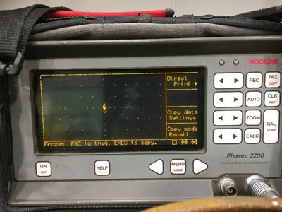
Figure 1. Signal from a defect-free sample.
All of the systems must be calibrated using appropriate reference standards – as for any NDT method and is an essential part of any eddy current testing procedure. The calibration blocks must be of the same material, heat treatment condition, shape and size of the item to be tested.
For defect detection, the calibration block contains artificial defects that simulate defects, whereas, for corrosion detection, the calibration block has different thicknesses. The eddy current method requires a highly-skilled operator - training is essential.
It is important to accurately measure the phase and amplitude of the signal in order to calibrate the probe, create the sizing curves, and estimate the depth of any flaws found during inspection.
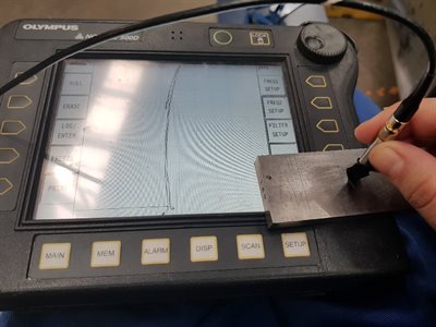
Figure 2. Checking the eddy current sensitivity.
There are a number of advantages with eddy current inspection methods for flaw detection and sizing:
- Able to detect surface and near-surface cracks as small as 0.5mm
- Able to detect defects through several layers, including non-conductive surface coatings, without interference from planar defects
- Non-contact method making it possible to inspect high-temperature surfaces and underwater surfaces
- Effective on test objects with physically complex geometries
- Provides immediate feedback
- Portable and light equipment
- Quick preparation time – surfaces require little pre-cleaning and couplant is not required
- Able to the measure electrical conductivity of test objects
- Can be automated for inspecting uniform parts such as wheels, boiler tubes, or aero-engine disks
- A single pass inspection can help reduce inspection times
- Can only be used on conductive materials
- The depth of penetration is variable
- Very susceptible to magnetic permeability changes – making testing of welds in ferromagnetic materials difficult – but with modern digital flaw detectors and probe design, not impossible
- Unable to detect defects that are parallel to the test object’s surface
- Careful signal interpretation is required to differentiate between relevant and non-relevant indications
- Inspection of parts or components including:
Welded joints
Bores of in-service tubes
Bores of bolt holes
Metal tubes
Friction stir welds
Gas turbine blades
Nozzle welds in nuclear reactors
Hurricane propeller hubs
Cast iron bridges
Gas turbine blades
- Detection of defects including:
Surface-breaking defects
Linear defects (as small as 0.5mm deep and 5mm long)
Cracks
Lack of fusion
Generalised corrosion (particularly in the aircraft industry for the examination of aircraft skins)
- Other applications
Identification of both ferrous and non-ferrous metals and with certain alloys – in particular the aluminium alloys
Establishing the heat treatment condition
Determining whether a coating is non-conductive
Heat treat verification of metals
An eddy current array (ECA) is an extension of conventional eddy current testing (ECT), consisting of an assembly of single eddy current sensors coils or sensors that allow the testing to cover a larger area in a single pass than conventional, single-coil probes, such as pencil probes.
However, this can lead to suboptimal results, so the probe assembly is multiplexed in a certain order to obtain the required sensitivity. Multiplexing is when the coils are activated and deactivated in set sequences to minimise interference between coils in close proximity (known as mutual inductance) while maximising the array probe’s resolution and attaining the greatest width.
There are many different designs of eddy current probes, including flexible probes, padded probes or spring-loaded fingers. With conventional eddy current probes, the coil in the probe acts as both a transmitter and receiver – these are called ‘impedance probes’ – whereas transmit-receive probes use separate transmit and receive coils.
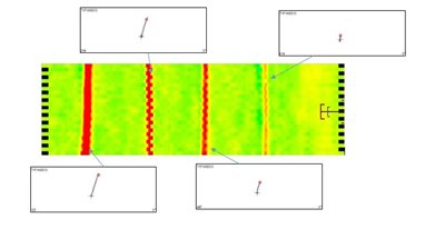
Figure 3. Calibrating eddy current array equipment.
- Reduction in inspection time, as:
The coils in the probe have been specifically arranged to cover a particular area
The scanning speed can be adjusted
A wider range of samples of can be inspected due to a wider range of probe types that are available
- Multi-frequency approach – possible to inspect a test object with several central frequencies simultaneously – allowing the user to assess the most optimised central frequency for the inspection, while multiple encoded scans can create a C-scan image
- Post analysis of results – the equipment’s built-in software enables the use of filters and other process to highlight or hide certain features
- Eddy current array inspections use advanced equipment that requires additional operator training
- Longer set-up time than a conventional eddy current inspection
Pulsed eddy current uses the same principle as conventional eddy current testing and methods are being developed to investigate surfaces through protective coatings, weather sheeting’s, corrosion products and insulation materials, using pulsed eddy current techniques.