Technical
What materials can be processed using CoreFlow™?
Aluminium AA6082-T6 and AA1050-H14 plates with a thickness from 5 to 50mm have been successfully processed and the application has already moved on to flat and tubular demonstrators that feature channels along linear, curved and helical trajectories. The demonstrators passed both leaking and pressure testing, with leak rates well below 10-8 mbar∙L/s and pressure up to 9 bar.
The process has been currently ported and tested on other aluminium alloys and on copper, which presents enhanced thermal properties with respect to aluminium. In addition, magnesium and titanium are the next metallic candidates on which the process will be tested.
Apart from metals, CoreFlow™ is expected to work also on thermoplastics. Friction Stir Welding (FSW) and Linear Friction Welding (LFW) of plastics is a proven and established technology already. The application of CoreFlow™ to thermoplastics like PEEK open a wide range of new possibilities to replace metals and ceramics in some applications. Uses include heat sinks on circuit boards, as well as tubing for heat exchangers in appliances, lighting, telecommunication devices, business machines, and industrial equipment used in corrosive environments. Of great interest is the application of CoreFlow™ on moulded parts.
What is the distortion compared to conventional channel forming techniques?
CoreFlow™ exploits friction in order to generate heat and plasticise the material around the probe, therefore it causes a certain level of distortion. The peak temperatures involved are similar to those of FSW, reaching up to 90% of the material melting temperature. However, with respect to FSW, CoreFlow™ heat profile is more localised. As such, the distortion levels expected from CoreFlow™ are akin to (or even lower) than those of FSW.
In terms of establishing a comparison with other processes for the manufacturing of embedded channels, machining from solid, followed by mechanical fastening or brazing a lid to seal the channel should have less distortion than CoreFlow™. If, instead, a fusion welding technology is used to seal the lid after machining, the peak temperatures experienced by the material will be higher than those of CoreFlowTM, which may contribute to a more significant distortion.
A trade-off might be found among several factors, including:
- Overall process throughput and cost
- Sealing reliability and pressure performance
- Maintenance costs associated with gaskets and bolts
- Additional costs of pre and post machining
Is there any deterioration in the mechanical properties due to the process?
A reduction of strength is observed in the HAZ when processing with CoreFlow™ heat treatable alloys (2xxx, 6xxx and 7xxx) in the T6 condition. This is not expected for T4 states or in strain-hardened alloys (1xxx and 5xxx).
Similar behaviour should be expected for other metals under investigation (i.e. Cu, Ti, Mg).
What is the processing speed of CoreFlow™?
The formation and geometry of the channel are influenced by the ratio between the probe rotation and its traverse speed.
In the beginning of the development, rectangular cross sections were produced for 15mm thick aluminium AA6082-T6 plates when combining rotation speeds of 400-600 rev/min with traverse speeds of 25-50 mm/min.
For a specific channel geometry, the process can be further optimised by increasing both traverse speed and rotation speed, therefore keeping their ratio constant. This optimisation, however, requires extensive efforts and its results will be limited to a specific material and probe dimensions. Moreover, increased performance and throughput could be achieved by changing the probe design, for example, by introducing additional features or by optimising the extrusion path.
By machining and re-sealing the cooling channels in a single step, CoreFlow™ consolidates multiple manufacturing operations, inherently offering an advantage compared to traditional technologies (e.g. milling, followed by sealing via brazing/bolting/welding). This creates a simpler process and a more efficient and environmentally friendly manufacturing method, using less raw materials, producing less waste, and therefore weighing less than its conventional counterpart manufactured by milling and sealing.
It might be noted, however, that CoreFlow™ is a novel process, under constant development. As a point of reference, it is worth mentioning that FSW, when invented at TWI in 1991, was a slow process compared to the mainstream fusion welding technologies. TWI’s heritage in innovation and process development allowed significantly boosting the speed of FSW after just a few years, drastically improving the process competitiveness. The key to unlocking faster processing speeds will be tool design, one of TWI’s key areas of expertise.
What is the surface roughness of the internal walls?
The figure below shows the surface profile of each of the internal surfaces from our trials on AA6082-T6 plates with a thickness of 15mm.
The bottom of the channel is the smoothest internal surface, exhibiting a Ra of 1.27 µm. This surface finish is consistent with the quality range provided by end milling (typically varying between 0.8 and 6.3 µm). A linear pattern of circular ripples produced by the leading edge of the probe can be observed on the bottom surface (subfigure a). The ceiling surface also exhibits a linear pattern of circular marks, although with opposing direction to that exhibited by the bottom surface (subfigure b). The ceiling presents a rougher texture, as reflected by the higher Ra value of 25.49 µm.
The side walls on the AS and RS present an Ra value of 18.61 and 25.11 μm, respectively. As shown in in the figure (subfigures c, d), both surfaces are characterised by a scale-like morphology, facing away from the direction of travel.
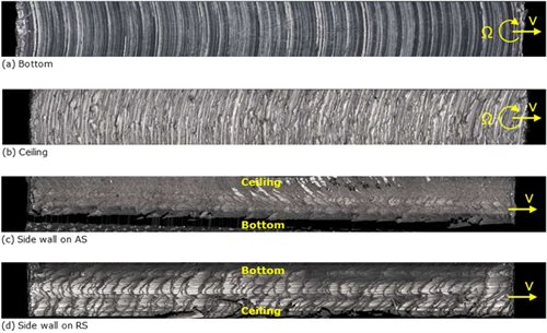
Channel inner surface roughness characterisation: (a) Bottom; (b) Ceiling; (c) Side wall on AS; (d) Side wall on RS.
Ensuring consistent and repeatable roughness values may enable this to be a design feature. Some heat exchangers are textured to promote turbulence in the coolant (as this flow regime enhances heat dissipation by convection). For products requiring laminar flow, TWI is developing methods of improving the inner surface finish via process optimisation or post-processing techniques. Some examples are chemical etching, abrasive flow machining (AFM) or fluidised bed assisted abrasive jet machining (FB-AJM).
How closely can two adjacent channels be positioned?
Channels separated by wall of material as thin as 1-2 mm have been successfully manufactured in AA6082-T6 with a thickness of 5 mm. However, different thermal effects were observed due to the accumulation of heat while reprocessing a small local area with several passes. Process optimisation is needed to mitigate this.
One of the latest research topics is the creation not just of channels, but also areas under the surface. This would be useful to form reservoirs in liquid transport/handling applications, embedding instrumentation or light-weighting of existing structures.
What are the properties of the wire by-product which CoreFlow™ produces?
TWI is researching if the material extruded from the plate in the form of wire can be used as feedstock for other processes, such as wire-based additive manufacturing or as a filler in fusion welding. CoreFlow™ is capable of extruding an unlimited length of wire from a plate or a pipe.
This process, labelled ForgeWire™, is of great interest for producing a spool of wire from materials with poor extrudability, such as alloys of aluminium or magnesium. Wire manufacturers or additive manufacturing process developers now have a quick option for producing wire with tailored chemical composition and from experimental alloy formulations (e.g. aluminium-lithium or aluminium-scandium), potentially even directly from the rolled product or cast billets.
What applications might CoreFlow™ be used on?
CoreFlow™ already sets to find revolutionary applications in the manufacture of heat exchangers, cooling systems, integrated fluid management and the light-weighting of structures.
Here a list of potential applications:
- EV battery trays with integral cooling channels built into the metallic structure.
- Incorporate channels in thin-walled electric motor casings for active cooling, reducing weight and improving motor performance.
- Aircraft engine cooling by channel networks incorporated directly in the nacelles.
- Hydraulic cooling systems allowing to replace hoses, pipes and fittings.
- Cooling of data servers, communication infrastructures and radar installations.
- Manage the thermal load in manufacturing equipment.
- Lubrication networks.
- Embedding instrumentation into a structure.
- Subsurface cable management.
- Additional light-weighting of existing parts.
Does CoreFlow™ require specialist equipment?
Trials have been conducted on an ESAB SuperStir™ machine (shown in figure below) with a purpose-built FSW gantry system fitted with TWI’s proprietary stationary shoulder system.
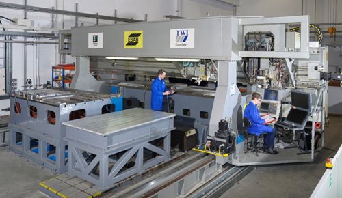
The probe used is a cylindrical proprietary cobalt-nickel-chromium alloy threaded probe, combined with a static flat shoulder . The shoulder featured four orthogonally-positioned, radial vent holes to enable the expulsion of the plasticised material. The probe and shoulder are designed specifically for the material to be processed and for the required application.
Next stage in the evolution of CoreFlow™ is the development of a universal head system for CNC drilling machines and robot arms, making the process implementable with a small capital investment. For FSW, universal head systems were already developed by TWI.
Robotic trials are already planned for next year, where ABB robots will be instrumented with a CoreFlow™ tool and used to embed channels in three-dimensional metallic surfaces.
Which channel geometries can be realised?
The channel cross-section geometry appears to vary from rectangular to triangular, depending on the parameters used. All channels feature a flat bottom surface, located consistently with the probe length depth used. The bottom of the channel presents well defined edges, coincident with the probe outline.
In future, additional shapes might be realised by changing process parameters and probe shape. Moreover, by changing the probe depth dynamically or in steps, 3D geometries might be achieved and channels might be created at several depth levels allowing for crossing and more complex patterns.
What is the maximum depth, width and ceiling thickness of a CoreFlow™ tunnel?
The dimensions of the channel, including its depth, mainly depends on the geometry of the probe. A rule of thumb regarding tools which are usually employed in FSW is that the aspect ratio should fall below 0.5, which means that its length could be slightly longer (up to 2 times) than its diameter. This, in turn, means that channel depth might be up to twice the channel width.
The ceiling thickness, however, depends also on the process parameters used and not only on probe design. Increasing the probe rotation speed, for example, will increase the extrusion rate, leaving less material behind in the channel and therefore creating a thinner channel ceiling.
Commercial
I do not know how to design for CoreFlow™ in my products – how can TWI help?
TWI provides everything from advice on component design, process selection and quality issues, troubleshooting, feasibility assessments and pre-production trials, application and prototype equipment development. TWI provides its Members and stakeholders with access to state-of-the-art in welding, joining, inspection and ancillary technologies, applicable across multiple industry sectors. Our research facilities also extend to assessment of structural integrity, and material characterisation.
With these capabilities, TWI can assist you in designing and prototyping the next generation of your products using CoreFlow™ as an enabling technology.
What is the IP status of the CoreFlow™ technology?
TWI has applied for patent protection in territories throughout the world, based upon PCT publication number WO2018083438.
How do I find out more about gaining a license to use CoreFlow™?
TWI intends to offer licences under the CoreFlow™ patents on a site-basis, in line with the FSW model. In this system, the licence fee would be determined based upon the number of sites at which CoreFlow™ is used (rather than based upon quantities of parts processed or products sold). However, TWI are always willing to review this arrangement on a case-by-case basis, aiming to prioritise technology adoption and dissemination.
For further information concerning licensing of this technology, please contact TWI’s IP department at ipr@twi.co.uk.
Are there any technical publications available on CoreFlow™?
Several technical publications have been prepared and published regarding CoreFlow™.
A TWI Insight article can be found at this link. https://www.twi-global.com/media-and-events/insights/coreflow-a-sub-surface-machining-process
Additionally, a scientific manuscript titled, “Developing a novel stationary shoulder variant of friction stir channelling” has been written by CoreFlow™ inventor Dr Joao Gandra and will be soon published in a scientific journal.