Assessing the integrity of subsea dissimilar joints to ensure safe operations
Amir Bahrami, Mike Gittos, Henryk Pisarski & Paul Woollin, TWI Ltd
Paper presented at Offshore Technology Conference, OTC 2010, Houston, TX, USA, 3-6 May 2010.
1. Abstract
Fusion welded buttered connections are an integral part of subsea oil and gas production systems and typically comprise a nickel alloy buttering weld deposit on an alloy steel forged hub, tee or elbow, which is postweld heat treated, and a nickel alloy closure weld, which is between the buttering and a pipeline steel (hence the term 'dissimilar joint'). In service, piping systems are protected by cathodic protection (CP). The CP provides a potential source of hydrogen which can be absorbed by the steel and, in the presence of sufficient amount of stress, can result in failure at the interface between the buttering deposit and the forging. In order to avoid future failures, it is important that the fracture mechanisms are understood and that there is a means of establishing fitness-for-service. The present paper describes the zones sensitive to hydrogen embrittlement (HE) in the buttering layer's partially mixed zone (PMZ) and summarises results of fracture mechanics tests carried out to assess HE of these interfaces, in seawater under seabed conditions. The paper further highlights the remaining issues that need to be addressed to ensure safe operation of these components.
2. Introduction
Subsea buttered connections are subject to CP, primarily using sacrificial aluminium anodes, which give an applied potential of approximately -1100mVSCE, which may result in HE, if the necessary conditions are met. The HE resistance of subsea buttered interfaces depends on three primary factors: material combination, buttering welding procedure and postweld heat treatment (PWHT)[1]. Each of these influences the microstructure and chemistry across the interface and unless specifically selected for resistance to HE, the joint is susceptible to failure. Whilst the vast majority of subsea joints have given successful service, a small number have failed. These failures have mainly involved installed components which have not been in service. [2]
Based on these failures, the combination of low alloy steel forging 8630M and buttering layer nickel alloy 625 has been has been found to be susceptible to HE and investigated in research programmes at TWI. Sensitivity to crack initiation and propagation is controlled by the chemistry and microstructure of the interface, especially the PMZ. Microstructures vary substantially throughout a joint and between joints [1 and 3] and, although they are undoubtedly influenced by welding and PWHT, no simple link between fabrication practice and sensitivity to HE has been established. Furthermore, it has been postulated that carbon has a significant influence on cracking sensitivity, and though low carbon content is now chosen, its influence has not been unequivocally established. There is therefore a need for a robust qualification test method, so that future subsea joints can be qualified for service, as appropriate, in addition to a clear understanding of the factors determining safe operation of existing subsea components.
3. Microstructure of the partially mixed zone
The microstructures of the dissimilar interfaces have been examined and previously reported.[1] The dissimilar interface can be divided into different microstructural zones with the PMZ being the most sensitive in terms of HE. The microstructure of a PMZ between 8630M buttered with alloy 625 is shown in Figure 1a.
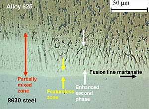
Fig. 1. The fusion boundary between an alloy 625 weld deposit and 8630 low alloy steel:
Fig.1a) Light micrograph showing detail of the partially mixed zone (PMZ) and
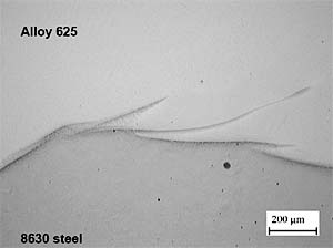
Fig.1b) Scanning electron micrograph illustrating swirls of steel-rich material extending into the weld metal
Starting from the alloy 625 buttering deposit towards the steel forging the PMZ comprises a region in the weld metal, containing numerous interdendritic Nb and Mo-rich phases (enhanced second phase zone).
There is a particle-free, highly carbon-enriched, featureless, austenitic region immediately adjacent to the fusion boundary (featureless zone).
A very thin (~1µm thick), steel-rich martensitic zone is present at the fusion line but more extensive martensite occurs in interfacial swirls, Figure 1b, where the higher melting range steel has been swept into the lower melting nickel alloy weld metal. Swirls tend to be created at bead overlap positions but variation in weld penetration also results in swirls with a complex and variable microstructure along the length of the first layer of buttering beads.
4. Susceptibility assessment
4.1. Appropriate test methodology development
A study, undertaken by TWI as part of a group sponsored project, focused on developing a suitable test method to reproduce failures that had been experienced, particularly in the North Sea.[4] In summary, three basic designs of test specimen were examined; circular cross section tensile, both smooth and with a circumferential notch and square-section bend fracture toughness specimens with EDM notches.[5] Testing was carried out; at slow strain rates and using stepped, sustained load tests.
Although all the tests were capable of reproducing the desired fracture morphology, when carried out slowly, the tensile tests produced a considerable scatter in the results, such that there was no clear relationship between failure time and applied stress. However, the use of electro discharge machining (EDM) notches in the fracture toughness specimens enabled more weld beads to be sampled reliably. Monitoring crack mouth opening displacement (CMOD), during the test, provided a useful comparison between fracture toughness and crack extension in air and in seawater under cathodic protection. On this basis, the slow bend fracture toughness test was identified as the most suitable for testing such interfaces. Details about this test are given in 4.4 below.
4.2. Materials
Initially materials from three North Sea hub type welds, which were of similar construction to those which had failed in service, were tested.[5] In addition joints were manufactured in a range of previously employed and current designs for buttered joints. [6]
4.3. Welding
Alloy 625, which met the requirements of AWS A5.14 ERNiCrMo-3, was used for most of the buttering deposits and all of the closure welds. One joint incorporated alloy 725 (ERNiCrMo-15) weld metal[5] and one alloy a low alloy steel filler material, meeting the requirements of AWS 5.28 ER100S-G, were included in the test programme. [6]
The buttering layers were deposited by mechanised, hot-wire, pulsed TIG welding, with a minimum preheat temperature of 150°C. PWHT was carried out at 665 to 676°C for 2 hours. The welding processes employed for the closure welds were manual GTAW for the root, hot and first fill passes and manual shielded metal arc welding (SMAW) for the remainder of the fill and cap passes.
4.4. Single edge notched bend (SENB) specimens
Fracture mechanics testing employed single edge notched bend (SENB) specimens, to generate both slow strain rate (SSR) resistance curves (R-curves) to evaluate crack initiation and propagation from a notch and KIH data to evaluate crack initiation from a notch under essentially constant load conditions.
To test joints with bevelled buttering layers, extension pieces were electron beam welded to each end of the test samples, in order to achieve the required length when cutting test specimens perpendicular to the buttering-steel interface. X65 material was used as extension on the forging side and grade 316 stainless steel was used on the buttering side. These specimens were cut such that the dissimilar interface was located at mid-wall.
Figure 2 shows a schematic of the test specimen.
Fig. 2. Bend test specimen geometry [5]
These test specimens have a 12mm (0.5in) square section and were prepared in accordance with BS7448 Parts 1 and 2. After machining, the coupons were etched in 2% nital to reveal the fusion line between the alloy steel and nickel alloy buttering to facilitate marking of the sample for notching by EDM. This notch was in the through-thickness direction, made using a 0.25mm (0.01in) diameter wire and 6mm (0.24in) deep. No fatigue pre-cracking was used since fatigue cracks have been found liable to deviate from the interface, thereby failing to sample the relevant zone.
All tests were performed in 3.5% NaCl with CP applied at -1100mVSCE. Typically the specimens were slowly loaded over a period of up to 24 hours at a constant temperature of 4°C. In addition, some slower displacement rate tests (25 to 50% of the slow strain rate tests) were carried out on two different material combinations employing the same procedure. These tests were designed to establish the influence of testing rate on the characteristics of the J-R curve. Normally, a series of specimens was employed to generate one R-curve.
4.5. Threshold stress intensity factor (KIH)
Incremental, dwell loading tests were carried out at 4°C in 3.5%NaCl aqueous solution under CP at -1100mVSCE, applied by potentiostat. Tests were conducted by loading samples in three-point bending to an initial stress intensity factor (K) within the range 40 to 50MPam0.5, depending on the dissimilar metal combination, holding this constant for a predetermined time (typically between 2 and 4 hours) and then continued by adding load increments to achieve an increase in applied stress intensity of 2 to 5MPam0.5.
Crack initiation was identified either from changes in the clip gauge-time trace or acoustic emission monitoring. Threshold stress intensities were calculated to obtain an estimate of KIH, that is, the highest K that can be sustained by the hydrogen charged specimen without initiating crack extension from the EDM notch.
5. Results
5.1. Fracture surfaces
Post-test examination of the fracture toughness specimens showed fracture face morphologies typified by those presented in Figure 3. Similar features were present when specimens intended for KIH testing were loaded above KIH. Two microstructural zones dominated the fracture path, one in the featureless zone and the other around martensitic zones. Fractography revealed terraced cleavage within the featureless zone and/or flat and contoured fracture at bead overlap interfacial regions, either directly at the interface or associated with swirls. These fractures seemed to have initiated independently and were found in most test specimens. The interface fracture associated with martensitic zones, was seen even in specimens that were not hydrogen charged and tested in air. Indeed, this is one of perplexing aspects of the tests conducted in air. The fracture faces reveal small patches of localised brittle areas but the global behaviour of the specimen under slowly applied loading conditions appears to be ductile. The significance of this merits further investigation.
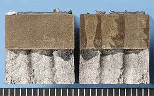
Fig. 3. Fracture faces of a SENB specimen
5.2. R-Curves
The J R-curves provided a means for discriminating between different materials in terms of resistance to crack extension from a notch due to HE. Depending on the slope and position of the R-curve along the fracture toughness axis in terms of J-integral, the dissimilar combination tested was classified into three groups, designated A, B, and C, as shown in Figure 4. For Group C, the resistance to crack extension was negligible in that the R-curves were flat or showed only a small gradient. Clearly such materials are expected to have poor resistance to HE. This contrasts to Groups A & B, which have significantly steeper slopes and initiation values and are expected to have significantly higher resistance to HE.
Fig. 4. J integral R curves for different material combinations
The chemistry of the featureless zone was found to be dependant on the dissimilar material combination, with some showing Ni-rich and some Fe-rich compositions. The Ni-rich compositions appeared to be associated with steeper gradient R-curves. Whilst the intercept of the R-curve appeared to be greater for those cases for which carbon content was expected to be lower.
Tests, which were carried out at a slower testing rate, revealed that, for a given material combination, the J R-curve became flatter with decreasing strain rate (see Figure 5), and lower J-intercept values were measured. That means that resistance to crack extension is decreased by lowering the straining rate. Despite this finding, the results obtained at faster rates (albeit still slow) have proved to be useful in helping to discriminate between material combinations and heat treatment conditions that are less or more susceptible to HE.
Fig. 5. Effect of strain rate on the resistance to HE of the dissimilar interface
5.3. Threshold stress intensity factor
For most of the interfaces, the KIH values obtained when tested in 3.5%NaCl at 4°C appeared to be less discriminating between materials than the R-curve tests. This could be related to the fact initiation from a blunt EDM notch was being measured. These data are being assessed currently but it appears that, compared with other material combinations tested, only the low carbon martensitic stainless steel forging had a significantly higher KIH value.
Another feature of the stepped loading tests was when loading was increased above KIH specimens fractured and this was not generally observed in the R-curve tests. Similar behaviour was observed in the limited number of stepped loading tests conducted without hydrogen charging but at much higher K values than those specimens that had been charged. It is possible that the residual hydrogen in the weld metal is playing some role in the fracture process.
6. Discussion
Crack propagation tests have been performed to derive J R-curves for a variety of joint types. However, these data have been derived using specimens containing relatively blunt EDM notches and, consequently, cannot be used to assess the significance of crack-like flaws that may arise at the interface. Furthermore, tests have shown the results to be strain-rate sensitive and a strain rate at which these rates become negligible has not yet been identified. Consequently, great care would have to be exercised in using such data fitness-for-service or engineering critical assessments (ECAs). Nevertheless, these data have been found to be very useful in ranking materials in terms or their expected resistance to HE. Similar comments apply to the KIH results where EDM notches are employed. Unpublished work comparing notches of differing acuities has shown that flatter R-curves are obtained from fatigue pre-cracked specimens. These findings suggest that a change to the testing procedure may be necessary in order to quantify the influence of crack-like flaws.
In addition, when failure occurs in the absence of flaws, conventional fracture mechanics cannot be applied and assessments through alternative methods, such as the application of micromechanical failure models, referred to as the 'Local Approach', might be applicable. Indeed, evidence from failure investigations of sub-sea dissimilar joints has not identified welding defects as being responsible. However, the role played by tensile stresses generated by the fabrication procedure is uncertain. Although the application of the local approach is attractive and may provide a clearer understanding of the stresses required to cause failure, it will be difficult to obtain the material properties, since the fracture process takes place in a very narrow, inhomogeneous, interface region.
Whilst various materials solutions have been proposed and put into service, the data supporting these solutions are predominantly from crack propagation tests on deep notched specimens, despite the fact that the relative importance of initiation and propagation in the failures has not been demonstrated. Indeed, it is likely that crack initiation is dominant and that, once initiated, a crack will propagate to failure, unless the operating conditions change.
The in-service performance of existing subsea connectors, e.g. to 8630 forgings, remains only partly explained. Whilst laboratory tests at 4°C show low resistance to crack propagation along the buttering interface, which provides a degree of comfort that the failures are understood, most such joints have given excellent service and the reasons for specific failures are not clear. However, it is considered that elevated operating temperatures are likely to be beneficial with respect to HE, compared to lower temperatures, typically endured after installation but prior to start-up. There is a need for data to substantiate this, to support on-going operations.
Another unresolved issue is whether HE susceptibility increases with water depth. There is some evidence from other materials, i.e. high strength steel and duplex stainless steel, that hydrostatic pressure increases hydrogen pick-up and HE susceptibility[7] but no data exist for dissimilar joints.
7. Conclusions
The work confirmed that subsea failures of dissimilar butter weld joints are a consequence of hydrogen embrittlement of microstructures developed at the steel/nickel alloy weld metal interface.
The unique factors that caused the field failures have not been identified. Uncertainty remains over the active stress, microstructural influences and extent of hydrogen ingress.
Further work is required to quantify the integrity of existing subsea connectors and to validate future materials selections. The stresses required to initiate cracking are required, together with appropriate hydrogen-charged fracture toughness data to allow acceptance of typical weld flaws.
8. References
- BeaugrandV C M, Smith L S and Gittos M F, 22-26 March, Atlanta, Corrosion 2009, NACE International.
- KvaaleP E and Rorvik G 2004 'Experience with qualification of and use of stainless steels in subsea pipelines' OMAE 2004 Vancouver.
- Beaugrand V C M, Smith L S and Gittos M F, May 31 - June 5, Honolulu, OMAE 2009.
- TWIGroup Sponsored Project Report 14403/13/06, 2006: 'Materials selection for dissimilar joints in subsea hubs - Final Report', June.
- GittosM. F., 2008, Resistance of dissimilar joints between steel and nickel alloys to hydrogen assisted cracking, Paper 08095 NACE 08 New Orleans.
- TWIProject Group Sponsored Project Report 17434/13/09, 2009: 'Design and use of dissimilar joints for subsea applications - Final Report', June.
- PohjanneP and Festy D, 1994: Hydrogen embrittlement of duplex stainless steel and maraging steel in sea water: effect of pressure, Corrosion 1994, NACE International, paper 223.