The Development of Lightweight Self-Piercing Riveting Equipment
S A Westgate
TWI Ltd
R Doo
Henrob Ltd
F Liebrecht, S Braeunling
Technical University of Dresden
T Mattsson
ABB Body-in-White (Olofström) AB
K-O Strömberg
Flexprop Production AB
SAE 2001 World Congress, Detroit, Michigan, March 5-8, 2001. 2001-01-0979
Abstract
Self-piercing riveting is an attractive joining technique in the automotive industry, particularly for materials which are difficult to resistance spot weld. The process is suited to robotic applications but because of the high setting forces required, conventional long reach guns would require excessive robot carrying capacity. A lightweight, long reach C-frame riveting gun has, therefore, been developed. Together with associated equipment improvements, increased suitability of the self-piercing riveting process has been demonstrated for the volume production of automotive components and body assembly.
Introduction
Self-piercing riveting is used for high speed mechanical fastening of sheet material components. It is suitable for joining dissimilar materials, as well as coated and pre-painted materials, and can also be used to join some plastics to metals. The riveting sequence is shown in
Fig.1.
Fig. 1. Schematic of self-piercing riveting sequence
The process has seen rapid development in recent years and is being used in a range of industrial and automotive applications. [1 to 3] In many cases, self-piercing riveting offers advantages over resistance spot welding. However, it has the disadvantage of needing high setting forces typically around 10 times those used for spot welding. Tool alignment also needs to be better. Thus, the C-frame on which the tooling is mounted needs to be sufficiently strong and rigid. This has limited the reach capability of conventional equipment that could be manipulated with a robot.
A European programme [4] , involving eight industrial and research partners, was conducted to develop novel equipment for self-piercing riveting and also to provide supporting data on joint properties. This work was conducted for self-piercing riveting on a range of materials with comparison to resistance spot welding where applicable. The influence of selected process factors on joint performance was also examined. Examples are given of these data. Best practice guidelines for self-piercing riveting were also compiled.
This paper presents details specifically of the design, fabrication and testing of the 850mm reach gun, with specific limitations on C-frame mass and deflection under the specified maximum load capacity of 53kN.
Specification
An initial specification was to build a lightweight C-frame which had an 850mm reach and be capable of applying 64kN at the load line. The maximum target weight was 90kg and frame deflection was limited to less than 7mm load line deflection and less than 1° angular deflection. Infinite fatigue life was also required.
A conventional steel C-frame met these requirements and a finite element analysis was conducted to establish the location and magnitude of peak stresses. In parallel, a novel design of composite C-frames were devised based on a revised specification with a weight limit of 80kg and a maximum force capacity of 53kN. Dimensional constraints and deflection limitations remained the same.
As the C-frame was relatively slender, buckling analysis was also conducted for up to 1° lateral misalignment at the tool.
C-Frame designs
The steel design comprised a symmetrical C shape with tapering arms (
Fig.2). Initial calculations indicated the requirements could be met with this basic shape, incorporating flanges, webs and stiffeners. Finite element meshes were generated using the Field Analysis Modeller (FAM) and analysed using the general purpose finite element code ABAQUS. Two-dimensional models were sufficient for the early design assessment, then three-dimensional (3D) models were used to predict the stresses in the webs and flanges accurately and to refine the design.
Fig. 2. Steel C-frame, principal dimensions
An example of the analysis is shown in Fig.3 for a stiffener and flange width of 60mm, and a web thickness of 8mm. Maximum stresses were 215N/mm 2 at the inside flange radius and 185N/mm 2 on the outside surface of the frame at the end of the stiffeners. In order to provide infinite pulsating fatigue performance of the steel C-frame the material strength can be estimated from standard data. A lower bound estimate of fatigue strength was 52% of the tensile strength in this case. Thus material strength needed to exceed 413N/mm. 2
Fig. 3. Steel C-frame, maximum principal stress contours, N/mm 2
The case of loading with a 1° misalignment of the frame caused offset stresses in the flanges and a peak operating stress of 374N/mm 2 was estimated. This required a material strength of 720N/mm 2 to provide infinite fatigue performance under such conditions.
The novel design of composite frame incorporated a steel skeleton with carbon fibre struts to provide stiffness in compression. This is shown in Fig.4. The skeleton is provided with aluminium alloy closing plates each side. This design was analysed and refined using ANSYS3D finite element analysis. The stress distribution in the frame is shown in Fig.5 and the maximum tensile stress was reduced to 195N/mm 2. The increasing throat gap near the front of the frame allows space for the rivet setter, while maintaining sufficient access for components between the rivet nose and die post.
Fig. 4. Composite C-frame showing steel skeleton and outer ring of carbon fibre reinforced composite struts. Near side cover plate removed
Fig. 5. Composite C-frame as in Fig.4, stress analysis shown for the steel component of the frame
The comparative data for the two frame designs are shown in Table 1.
Table 1. Comparison of C-frame designs
| | Steel Frame
( Fig 2 ) | Composite Frame
CCF850 ( Fig 4 ) |
|---|
| Mass, kg |
89 |
78 |
| Maximum force capacity, kN |
64 |
53 |
| Reach, mm |
852 |
850 |
| Load line deflection, mm |
7.8 |
6 |
| Load line angular deflection, degrees |
0.78 |
0.75 |
| Fatigue life |
infinite |
infinite |
| Deflection under oblique loading*, mm |
2.13 |
2.01 |
*Out of plane deflection at the centre of the load line caused by assuming the respective maximum force values were applied with a 1° misalignment between the loading points.
Evaluation
Laboratory testing
The composite design was chosen for development and, following optimisation of the design by 3D modelling, a prototype gun was manufactured. This underwent initial static loading with deformation and stress measurements to provide verification of the model. The gun was then bench mounted and equipped with a riveting actuator to apply load between the dummy nose of the setter and the die post. The unit was cycled at its maximum force capability (53kN) to provide an endurance test for the frame. Two problems were revealed by this test and the supporting analysis. High stresses in the adhesive bond of the sandwich spar steel/C-composite/steel were a cause for concern and a fatigue failure occurred from in the setter block because of a poorly positioned fixing hole. Design refinements eliminated these problems and the frame completed two million cycles.
Design improvements to the riveting system
Refinements were made to the nose and die holder design on the riveting system to improve access to the component during rivet setting. The nose assembly in its retracted position for rivet loading are shown in
Fig.6. An improved blow feed unit was developed having a specially designed feed tube with a T-section bore. The material was chosen to provide good flexibility, lightweight and good wear resistance. The tube was normally capable of accepting rivets of 5mm diameter in a range of lengths. Head profile was normally countersunk but alternative designs could be delivered through the same tube.
Fig. 6. Nose assembly and rivet feed mechanism on the prototype composite gun.
A new type of blow feed rivet delivery mechanism was devised to position rivets in the nose ready for setting and sensors ensured the presence and correct location of the rivet prior to the setting operation.
In order to allow compliance of the die against the material being riveted, when the gun was robot mounted, a compensating cylinder was provided between the mounting plate and the frame. Regulated air pressure to this cylinder counterbalanced the gun weight. The pressure could be programmed for different gun orientations depending on the robot position. This compensation prevents component distortion if the die is not positioned in contact with the component, and also allows for the flexure of the gun arms.
In parallel with the gun development, a second generation prototype process monitor was developed. This was a compact dedicated microprocessor unit which sampled the hydraulic pressure and punch displacement continuously during the setting operation. By means of a special algorithm, selected features of the monitored signals could be used to identify the most likely cause of any deviations from standard preset conditions. Additional counting and maintenance warning functions are included.
A laboratory evaluation of the monitor was undertaken. This showed that significant changes in rivet length and die shape could be detected. Substantial additional work would be required to establish the extent to which such a monitor could detect variable quality factors such as variation in rivet/button profile and mechanical properties of the joint. Continuous improvement of the monitor has included increased sampling rate and resolution of the monitor signals, detection of the initial material thickness and a means of compensating for gun deflection during setting.
Factory evaluation
The gun assembly was mounted on an ABB IRB 6400 robot on a track motion for proving trials under factory conditions. The total weight of the riveting equipment including tool changer was 164kg. This was slightly greater than the 150kg payload capacity, but it was possible to conduct riveting trials on test panels in both the horizontal and vertical planes. The test set-up is shown in
Fig.7.
Fig. 7. Set-up for factory trials of the prototype composite gun
The materials riveted were 1mm hot dip galvanised low carbon deep drawing steels. On the rivet head side the steel was 330N/mm 2 maximum tensile strength with a 20µm zinc coating and on the rivet tail side the steel was 315N/mm 2 maximum tensile strength with a 10µm zinc coating. The forces applied by the riveting tools were nominally 6.8kN for clamping and 46.1kN for setting. Thus the gun was working at its maximum rated force of 53kN.
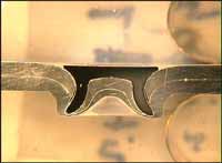
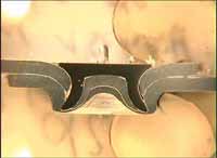
During the trials 86,000 rivets were set and test samples were produced every 1000 operations to measure shear and peel strength and to measure features of the joint cross-section. The mean shear strength of the joints was 3.37kN with a 3 x standard deviation value (3 σ) of 0.56kN. The mean peel strength of the joints was 2.51kN with a 3 σ value of 0.37kN. The dimensional information from the cross-sections was analysed and found to be consistent. The rivet head was set down typically between 0.1 and 0.4mm below the sheet surface. The tail of the rivet did not break through the lower sheet although the remaining metal was typically less than 0.1mm thick. The deflection of the gun (6.9mm) did not adversely affect the joint appearance as the angular misalignment was small (0.7°). The performance of the equipment was recorded and any faults were logged. A few problems were encountered but these generally required little maintenance. Slight refinements to the rivet feed system were made during the trials to improve components which were subject to the highest wear conditions. During the trials of this prototype assembly, the technical availability was 96% (this was defined as operating time/total time, i.e. 4% downtime). The technical efficiency was 99.96% (this was defined as correctly set rivets/total riveting cycles, i.e. 0.04% failure stops).
Further frame developments
On completion of the composite gun frame, further design options were considered, particularly with a view to minimising the angular deflection at the riveting tools. The open frame concept was refined and modelled in steel for a 450mm throat depth C-frame, see
Fig.8. An optimised design was achieved which gave only in-line deflection of the arms with virtually no angular deflection. This design is shown in
Fig.9 in comparison with a conventional C-frame. Both designs had 70mm wide flanges and the conventional unit 15mm thick webs. Deflections were calculated under axial loading of the tool posts with 53kN force, and under oblique loading with a 1° imposed misalignment of the load axis.
Table 2 shows comparative details of the C-frames. A prototype ACF450 has been built and is undergoing evaluation.
Fig. 8. ACF 450 development steel C-frame, maximum principal stress contours, N/mm 2. Deformation is amplified 10 times
Fig. 9. Conventional type C-frame (a) and ACF450 development (b) compared for out of plane load/deflection modelling
Table 2. Comparison of C-frame designs. Deflections measured under 53kN applied load, oblique loading due to 1° imposed misalignment of the load axis.
| | C-Frame |
|---|
| ACF450 ( Fig.9b) | C450 ( Fig.9a) | CCF850 ( Fig.4 ) |
|---|
| Throat depth, mm |
450 |
450 |
850 |
| Total axial deflection, mm |
4.85 |
2.43 |
6.02 |
| Total lateral deflection, mm |
0.06 |
0.10 |
0.59 |
| Total angular deflection, degrees |
0.012 |
0.52 |
0.75 |
| Lateral deflection (oblique loading), mm |
0.92 |
1.54 |
1.54 |
Self-piercing riveted joint properties
In parallel with the equipment development work. Joint properties were evaluated for a range of material combinations of particular interest to the automotive industry, see Table 3. Results were generated for static and fatigue properties in comparison to resistance spot welding. [5] Figures 10 to 13 show typical data. Nominally 5mm shank diameter countersunk steel rivets were used throughout and a press frame riveting equipment was used. The work also incorporated data on hybrid joints with spot welds or rivets plus adhesives, e.g. Fig 14. Riveted joints were also produced in aluminium to steel and in lightweight composite sheet (steel/plastics or aluminium/plastics).
Table 3. Material combinations studied
| Combination | Material thickness and type |
|---|
| 1 |
0.7mm LCS to itself |
| 2 |
0.8mm Zn-coated LCS to itself |
| 3 |
0.8mm Zn-coated HSS to itself |
| 4 |
1.2mm Zn-coated HSS to itself |
| 5 |
2.5mm HSS to itself |
| 6 |
0.8mm Zn-coated HSS (3 thickness joint) |
| 7 |
1.2mm Zn-coated HSS to 2.5mm HSS |
| 8 |
0.8mm Zn-coated HSS to 2.5mm HSS |
| 9 |
1.2mm 6016 Aluminium to itself |
| 10 |
3.0mm 5754 Aluminium to itself |
| 11 |
1.2mm 6016 Aluminium to 3.0mm 5754 Aluminium |
| LCS - low carbon steel, HSS - high strength steel |
Fig. 10. Failure loads for resistance spot welded and self-piercing riveted joints tested in tensile shear
Fig. 11. Failure loads for resistance spot welded and self-piercing riveted joints tested in T-peel
Fig. 12. Load-endurance diagram for steel joints
Fig. 13. Load-endurance diagram for aluminium joints
Fig. 14. Load-endurance diagram for 0.8mm thick zinc coated steel
Influence of process parameters
Investigations were made into selected process variables. Data exist for key factors such as tooling alignment [6] but this work examined additional factors including material thickness and properties, rivet hardness and edge distance. Changes in material thickness influenced the appearance of the cross section of the joint but there were no apparent problems over a thickness range of ±20%. Joint strength increased in proportion to thickness as might be expected.
The effect of edge distance is shown in Fig.15. Reasonable joint appearance was achieved in all cases. However, static joint strength was reduced by around 30% at the closest edge distance (5mm) because of the reduced support of the parent material around the joint.
Fig. 15. Results for the influence of edge distance on riveted joints in 1.2mm 6016 aluminium alloy
Task 2
Influence of process factors |
TU Dresden
Instut für Produktionstechnik
Dipl.-Ing. Fritz Liebrecht |
| Technique: Self-Piercing Riveting |
| Effect of edge distance |
Parameters: |
| type: |
Al Alloy 6016
(TWI batch number L4135) |
diameter [mm]/length/[mm]/hardness
rivet: 5 / 5 / H2
die: DZ 9-0.25 |
| layer: |
top |
bottom |
setting force: 41 kN
clamping force: 13.5 kN |
thickness
[mm]: |
1.2 |
1.2 |
| |
 |
| Edge distance (X), mm |
10 |
| |
| Mean shear load, kN |
2.98 |
| Mean peel load, kN |
1.27 |
 |
| |
 |
| Edge distance (X), mm |
7.5 |
| |
| Mean shear load, kN |
2.73 |
| Mean peel load, kN |
1.08 |
|
|
| |
 |
| Edge distance (X), mm |
5 |
| |
| Mean shear load, kN |
2.17 |
| Mean peel load, kN |
0.87 |
Conclusions
- A lightweight long reach C-frame based on a composite design was successfully designed, built and demonstrated for robot mounted self-piercing riveting equipment.
- Such equipment is within the capability of currently available robot capacity, and there is scope for further reduction in weight with refinements of design of the frame itself and the associated equipment.
- The equipment demonstrated the desired endurance and, apart from minor maintenance problems associated with the prototype nature of some of the components, showed excellent performance on initial factory trials.
- Over a range of thin sheet material combinations, the static shear and peel properties of self-piercing riveted joints using 5mm diameter rivets compared favorably with resistance spot welding, and exceeded spot weld strength in thin aluminium alloys.
- The fatigue strength of the self-piercing riveted joints significantly exceeded that of spot welds for all material combinations tested except the thickest steel (2.5mm) where a 5mm rivet was compared to an 8mm diameter weld.
- The effect of selected process variables on weld strength and appearance was demonstrated. Edge distance had a strong influence on joint strength, for example.
Acknowledgments
The results presented in this paper were obtained in the SPRYTE (Self-Piercing Riveting and Hybrid Joining Technologies) project. This project was a collaboration between ABB Body-in-White AB; Flexprop Production AB; Hanteck Ltd; Henrob Ltd; Hoogovens Corporate Services BV; Permabond Ltd; Nordisk Industrirobot Scandria AB; Technical University Dresden; and TWI. The project was co-ordinated by Henrob Ltd, managed by TWI and funded by the European Commission under the CRAFT programme (reference BRST-CT97-5088) and by in-kind contributions from the partners.
References
1. Litherland H: 'Self-piercing riveting for aluminium applications'. INALCO '98 Proceedings, 7
th International Conference, Cambridge, 15-17 April 1998, 135-147.
2. Zeitzmann D: 'Use of mechanical joining techniques within Mercedes-Benz' Advanced Technologies and Processes Proceedings, International Body Engineering Conference IBEC '97, Stuttgart Germany, 30 September - 2 October 1997, 78-82.
3. 'Say Audi to the new space frame'. Welding and Metal Fabrication 2000 68 (3) 11-13.
4. 'Self-piercing riveting and hybrid joining technology (SPRYTE)'. Craft Project BRST CT97-5088 (DG12 CZJU).
5. Booth GS: 'Self-piercing riveted joints and spot welded joints in steel and aluminium'. International Body Engineering Conference and Exposition. Detroit September 2000.
6. Hahn O and Voelkner W: 'Untersuchung zur Optimierung des Stanznieten mit halbhohlniet als universelles Fuegeverfahren zum Verbindung von Blechen und Profilien' (Study of the optimisation of semi-tubular self-piercing rivets as a universal joining method for sheets and profiles) EFB Forschungsbericht No. 85, 1996