Paper presented at NAFEMS 2010, Oxford, UK. 8-9 June 2010.
Summary
Welding of thick-walled components tends to generate large regions of high tensile residual stresses which can promote the possibility of brittle fracture or corrosion cracking. The magnitude of the residual stresses can be reduced by post-weld heat-treatment (PWHT). When the component is too large to be furnace heat-treated, local PWHT of a circumferential band (for a pipe) or a circular patch (for a header) is permitted by some codes and standards. British and American codes recommend procedures for local PWHT, including the size of the heat-treated zone. Following these recommendations should avoid the generation of residual stresses of significant magnitude in the zone of the local heat-treatment.
There is an industrial demand for reduction of the size of the heat-treated zones, either to protect existing connections and heat-sensitive attachments, or to reduce energy consumption. However, the temperature gradients can be harmful and Finite Element Analysis (FEA) can be used to optimise the heat-treatment procedure by predicting the residual stresses.
The current paper presents the use of FEA to calculate the residual stresses after local PWHT of a branch-pipe connection. Constant and variable width soak bands have been investigated. Analyses were performed assuming either elastic, or elastic-plastic and creep materials models. Residual stresses were predicted and the results were compared using different criteria issued from standards and publications.
1: Introduction
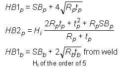
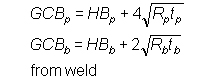
The British codes give the size of the heat-treated band; the American codes give the size of the soak band, where the specified HT temperature shall be met. The table below summarises the recommended size of the soak band (SB), heated band (HB), where heated elements are applied, and gradient control band (GCB), that includes the heated band and the insulation pads.
| | Soak Band (SB) | Heated Band (HB) | Gradient Control Band (GCB) |
|---|
| BS2633 |
|
 |
½ Tmax at the edge of HB |
| PD5500 |
|
 |
½ Tmax at the edge of HB |
| ASME B31.1 |
SB = 2t |
|
Avoid harmful gradients |
| ASME B31.8 |
SB = 102mm |
|
T shall diminish gradually |
| ASME I |
SB = inf(2t, 102mm) |
can be larger than SB to avoid harmful gradients |
Avoid harmful gradients |
| AWS D10.10 |
SBp = inf(2tp , 102mm)
SBb = inf(t b , 51mm)
from weld |
 |
 |
2: Procedure for modelling local PWHT
The pipe was assumed to be 360mm in diameter and 63mm in wall thickness. The branch was 63mm in diameter and 100 mm in wall thickness. The material was assumed to me 0.5Cr-0.5Mo-0.25V steel.
Circumferential bands measuring 250mm or 510mm from the weld, triangular bands measuring 510mm (but with a narrow soak band) or 300mm at the top, and patches whose radii were 300mm, 355mm, 410mm, or 465mm were assumed for heat transfer analyses. Figure 1 shows some of the steady state temperature profiles obtained.
The stress analyses were elastic, starting from zero stress at heat treatment temperature, or elastic-plastic, with stress relaxation, starting from the initial residual stress field, and modelling full thermal cycle. The results obtained show that the residual stress fields are very similar for the four patch sizes investigated, and no significant difference was observed when comparing the results obtained with both circumferential band widths. However, results vary with the geometry of the heated zone. Figure 2 shows the highest residual stress predicted for four heat treatment zones. Except for stress concentration at the weld toe (e), the residual stress generated by the temperature gradient is usually lower when using the elastic-plastic than the elastic analysis. it is also of the same order or below 0.3y (value recommended by [BS7910, 2005]), 0.05ET0 (used by [Burdekin, 1963]) or 0.5y (used by [Cotterell, 1963]), except for the case where the soak band was controlled to be 75mm.