by Amir Bahrami
Paper presented at Deep Water Technology Conference, Asia, Kuala Lumpur, Asia, 26-27 Oct. 2009
Introduction
Steel Catenary Risers (SCRs) are a viable solution for production and export of offshore hydrocarbons in many deepwater developments. However there are still some challenges in the design of SCRs with the most prominent of all being fatigue.[1] SCRs are subject to fatigue loading due to vessel movements, wave and tidal motions and vortex induced vibrations (VIV). Their fatigue life is controlled by the behaviour of the girth welds where even the development of a single through-wall crack could have serious environmental, safety and cost implications. This is because unlike many welded offshore structures such as jacket structures traditionally employed in shallow waters, SCRs have no redundancy in their design, and failure of one girth weld will result in failure of the whole system. The analysis and design of deepwater risers against fatigue is typically conducted according to industry standards and codes such as BS7608 and more detailed design, fabrication, installation and operation practices are devised and followed by operating companies.[2] Much effort is placed during the engineering phase of a project to ensure adequate quality and fatigue performance of SCR girth welds through the following activities[3]:
- Weld procedure qualification
- Reducing the amount of joint misalignment
- Engineering critical assessment
- Inspection
- Fatigue qualification testing
The fatigue performance of a given girth weld is then rated against the fatigue design curves, these curves originated from TWI over 3 decades ago. They were based on data obtained from welded plates in different configurations, with the butt weld data coming from specimens with double sided welds. These design curves were subsequently adopted by many standards including DEn (HSE), and DNV (
Figures 1 and 2).
Figure 1. Fatigue design curves used for girth welds
Figure 2. Current fatigue design S-N curves (BS7608 classifications) for girth welds compared with some fillet welds.
Parameters influencing fatigue performance of girth welds
Welding process
In general the welding process does not affect fatigue performance, but depending on the likely location for a fatigue initiation site, the quality of the weld, in terms of presence of flaws, would be expected to affect the fatigue life. Fatigue of seamless riser pipes usually initiates at the root, therefore the quality in terms of bead height; re-entrant angle at the toe and presence of planar defects such as lack of penetration or sidewall fusion significantly affects fatigue.[6] Figure 3 illustrates the effect of root quality on fatigue performance although presence of such flaws in a production girth weld is very unlikely and the figure is purely for illustration purposes. GTAW usually gives good root quality but it has a low productivity so it can be used for the root pass while the weld is completed using SMAW or GMAW.[7] Another attractive process is mechanised narrow groove GMAW made on copper backing shoes on the pipe ID.
Figure 3. Effect of root quality on fatigue performance
Referring to Figure 2 it can be seen that single-sided welds made on permanent backing are given Class F while those made without backing are classed as F2 due to concerns over joint misalignment and poor weld root condition. This choice is not based on actual fatigue test data and could be over-conservative for situations in which full penetration welds with favourable root geometries can be guaranteed[8,9] (e.g. those produced using modern, mechanised pipe welding). Recent research suggested that it is possible to achieve Class E curve when allowance for misalignment is made in the calculation of the relevant stress range and hi-lo is controlled within 0.5mm.[10] TWI is currently undertaking a study to establish which of the current curves are most applicable based on the results of more than 2000 full-scale tests.
Misalignment
Misalignment between the pipe ends to be welded introduces a secondary bending stress, which augments the membrane stresses in the pipe. The axial misalignment is the most important form of misalignment, which mainly occurs due to mismatch in wall thickness and ovality.
For design purposes, a stress magnification factor (km) on the applied stress for diameter to thickness ratio values typical to pipelines, is found using the equation, which has already been included in NORSOK N-004:
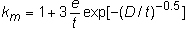
Where e (eccentricity) is the axial offset, D is the pipe diameter and t is the pipe thickness.
It is usually difficult to achieve km <1.2 for most seamless pipes in as welded conditions unless there is a special matching for the pipes to be welded. Attention to machining and matching of pipes can improve misalignment due to eccentricity, as can using extruded or forged and machined pipes.
Fatigue data from studies of the effects of intentional misalignment in butt-welded plates are presented in Figure 4. [11]
Figure 4. Review of fatigue data obtained from transverse butt welds allowing for misalignment.
To achieve the desired fatigue life in a riser, high quality welds with minimal amounts of misalignment are necessary but not sufficient; the other most important requirement is a high quality inspection in terms of reliability, resolution and probability of detection.
Inspection
Automatic ultrasonic testing (AUT) is typically employed to detect critical flaw sizes (on the ID) as small as 0.5 to 1mm in height, which is a possible requirement for highly fatigue critical SCR welds. Qualifying AUT systems and operators for such flaws and establishing the practical limits of the system takes a long time, requiring inspection and sectioning of several test welds and operators, this makes the establishment of the fatigue criterion a long lead item of design.
Flaw assessment
ECA analysis is typically performed as per BS7910[13] to determine the welding flaw acceptance criteria. The ECA analysis uses the Paris law to model crack propagation:
da/dN = C(ΔK)m
Where, da/dN is the growth rate, C and m are constants and ΔK is the stress intensity factor.
The acceptance criterion will then define the maximum acceptable size of initial flaws, ie ones that calculations show will grow to the critical size over the design life of the structure (including appropriate safety factors).
Some embedded volumetric flaws and shallow weld toe undercuts may be acceptable and the recommended levels corresponding to the design S-N curves related to girth welds are given in Table 1.
Table 1. Acceptance levels for volumetric flaws (BS7910) [5]
| Design Class | Flaw acceptance limit | | |
|---|
| |
(porosity*, % area on radiograph) |
Slag inclusion length, mm |
Undercut (depth/w.t.)** |
| D |
3 |
2.5 |
0.025 |
| E |
3 |
4 |
0.05 |
| F |
5 |
10 |
0.075 |
| F2 |
5 |
35 |
0.1 |
*Individual gas pore size less than t/4 or 6mm.
** Maximum allowable depth = 1mm. |
Residual stresses
Normally the magnitude of the tensile residual stresses induced by welding increases with increasing size or thickness.[14-17] However, in the case of welded pipes numerical analyses and stress measurements indicate that the residual stresses at the roots of single-sided girth welds, usually the critical location with respect to fatigue, tend to decrease and even become compressive as the wall thickness increases. Compressive stresses on the ID can improve fatigue life of the weld root but due to a large scatter in data obtained for residual stresses this benefit cannot be used in design.
Qualification fatigue testing
In general fatigue tests can be performed either as endurance tests using strips cut from a pipe or full scale pipes, resulting in S-N curves showing number of cycles to failure for a specific stress range. However S-N strip samples exclude the size and volume effects (larger samples will have higher probability of carrying more critical flaws) as well as producing non-representative residual stresses, which will influence the effective stress range. Therefore strip tests might produce non-conservative data particularly in the long life regime and therefore full-scale testing is required.
Corrosion fatigue qualification testing is usually a two-stage process involving full-scale resonance fatigue testing to demonstrate the required performance in air, and strip fatigue testing both in air and in a corrosive environment to determine a fatigue life reduction factor that is then applied to the base design curve. There is however a need to validate small-scale test data by testing full scale girth welds in a representative environment and thus develop riser fatigue design guidance for various corrosive service environments. Current research is underway at TWI to address this issue.
In service loading and effects of VIV stresses
In terms of in service loading Miner's rule is generally used to estimate the accumulated damage due to different loadings in a variable amplitude (VA) spectrum and the fatigue performance is satisfactory if Σn/N ≥1. However recent work[18] has shown that when stress cycling down from a high tensile stress as illustrated in Figure 5 (sequence A: cycling down from a constant max stress) Miner's rule is not conservative enough. However when stresses cycle up from a constant minimum stress (sequence C: increase mean stress with increasing stress range) Miner's rule is conservative and cycling about a constant tensile mean stress gives slightly non-conservative results (Sequence B). Therefore Miner's rule is deemed non-conservative under certain loading conditions particularly when higher stresses are followed by lower stresses in a spectrum (variation in applied mean or maximum stress are of secondary importance to stress sequence). [18]
Figure 5. Comparison of variable amplitude test results with the constant amplitude S-N curve expressed in terms of the equivalent stress range. [18]
From a practical viewpoint, the nature of the fatigue loading on risers is such that fatigue in the low stress regime of the S-N curve is dominant, however once a crack is initiated under larger stresses then even stresses below constant amplitude fatigue limit (CAFL) will become damaging.[19]
Therefore an assumption is made when dealing with low stresses to either using a lower band bi-linear S-N curve with a change of slope form m to m+2 or extrapolating the constant amplitude SN curve with no fatigue limit as illustrated in Figure 6. Currently significant research is under way at TWI using full scale testing under representative conditions to quantify the effects of VA and VIV on fatigue performance of girth welds in air.
Figure 6. Fatigue design curves for variable amplitude loading
Corrosion fatigue
Risers are exposed to aggressive environments on both the outside surfaces (ie seawater) and the inside surfaces (ie produced fluids). Unlike fatigue in air, fatigue in corrosive environments is affected by material-environment interactions and the microstructures developed at a welded joint may contribute significantly to its corrosion fatigue properties. [20]
Two of the main mechanisms by which corrosion fatigue may reduce fatigue performance are crack tip dissolution and hydrogen embrittlement. The former occurs by general crack tip dissolution in C-Mn steel and crack-tip passive film rupture in CRA materials, such as stainless steel, where localised plastic straining ruptures the protective film and promotes dissolution. On the other hand the hydrogen generated at the crack tip due to corrosion or the hydrogen that has diffused into the crack from other production sites (e.g. adjacent surfaces by cathodic protection or as a result of corrosion in sour service) can enhance fatigue damage by embrittling or weakening the material at the crack tip.
The primary environmental factors that are important include the pH and partial pressure of H2S, together with Cl- content, temperature, and partial pressure of CO2. Since risers made from C-Mn steel will be inhibited, the effects of inhibitors, and of occasional lapses in inhibition, are also important.[22] Due to the complicated interaction of these variables extrapolation from one condition to another is very unreliable, and design of girth welded SCRs for corrosion fatigue service currently requires development of project-specific data.
Seawater
Extensive fatigue endurance and crack growth data for carbon steels in seawater have led to comprehensive design guidance. However, most experience is confined to North Sea wave loading conditions (water temperature of around 5°C and a cycling frequency of 0.15-0.5Hz).[23] As shown in Figure 7 in air performance can be restored by cathodic protection in seawater only at low stresses and there is no benefit at higher stresses. Indeed, cathodic protection might even be more harmful than free corrosion at high stresses due to hydrogen embrittlement, especially in high-strength steels. In general the fatigue lives of welded joints are reduced in seawater, with or without cathodic protection by a factor of three at high stresses, at 5°C and even more at higher temperatures. [23]
Figure 7. Examples of design S-N curves for steel welded joints operating in seawater. [23]
Sour (H2S-containing) environments
The effect of sour environments at relatively low temperatures, and even at relatively low H2S concentrations is very significant, when compared to performance in air, with degradation factors on life of between 10 and 100.[27] Combined high cycle fatigue (HCF) and low cycle fatigue (LCF) data from in Figure 8[27], suggests that the use of a straight line S-N curve for sour conditions represents a reasonably conservative assumption for design. Further qualification testing could then be conducted in the more practical intermediate-cycle fatigue (ICF) regime. There is only a limited amount of data applicable to flowlines in sour environment available in the public domain,[28] although unpublished data exists for many candidate SCR materials under various service conditions as a result of several TWI joint industry projects.
Sour service results in significant hydrogen charging of steel, and hardness is likely to be the dominant materials parameter; at least for C-Mn steels, but local grain size and composition may also be significant in corrosion fatigue of CRAs.[22] The detrimental effect of H2S increases with increase in ΔK, applied stress ratio and decrease in cycling frequency. [24,25,26]
Figure 8. Sour endurance data for HCF and LCF. [27]
Sweet (CO2-containing) environments
In these conditions, the corrosion fatigue crack extension mechanism is primarily due to anodic dissolution of the crack tip and is significantly influenced by the precise environmental conditions. It has been shown[29] that under very highly corrosive conditions, in which no protective scale was developed, fatigue endurance may be increased, and this was explained in terms of a competition between fatigue crack growth, and removal of the damaged material by corrosion. However if the balance of fatigue and corrosion conditions is changed, acceleration of fatigue can be observed (Figure 9). Thus, in these environments it is important to ensure that the scaling conditions are correctly modelled, and that the effects of inhibitors are taken into account. Scaling conditions with and without inhibiter are currently under investigation at TWI. There is limited evidence to suggest that the presence of inhibitor reduced crack growth rate in one particular sweet environment.[29] However it was only effective at low K and only if present prior to any significant pre-corrosion.
Figure 9. Fatigue endurance test data for an API 5L X65 material in pH of approximately 4.5 at 60°C. [29]
Pipe materials
With increasing water depth, produced fluid corrosivity and challenges facing SCRs (fatigue, corrosive service, strength, cathodic protection, weight on the hull, etc.), high integrity is required and materials other than the carbon steel may become attractive, including clad pipes, stainless steels, and titanium. The majority of the current, limited published data are based on the performance of carbon steel with a limited number of studies on different types of stainless steel. [30]
Fatigue crack growth rate testing of duplex, superduplex and supermartensitic stainless steels indicates that environments including 3%NaCl, seawater with cathodic protection and deoxygenated sour brine may all give increased weld area fatigue crack propagation rates relative to air by a factor of 3-10 depending on the environment and the material tested, presumably as a consequence of passive film rupture at the crack tip. In all of the tests, crack growth rates in the various environments were closer to the air data in the near threshold region than at higher stress intensity ranges. Existing data suggest that austenitic stainless steels and nickel alloys may be preferred materials for corrosion resistant SCRs operating in sour service due to their low susceptibility to hydrogen embrittlement by the internal environment. Full size endurance testing is required to give a more complete understanding of the corrosion fatigue behaviour of girth welds in candidate stainless steels for riser applications [30]. Unpublished work at TWI has also indicated that highly corrosion resistant materials such as 625??? clad can have superior fatigue performance to both carbon steel and stainless steels in sour environments.
Conclusions
Primarily for economical and practical reasons, SCRs are always fabricated using single-sided girth welds. Historically, most fatigue design rules have penalised single-sided butt welds. However, there is growing evidence to show that single-sided girth welds made under carefully controlled conditions can perform much better than their nominal design curves (namely F or F2) suggest.
The adoption of higher S-N curves requires confidence in the consistent achievement of high quality girth welds. Quality is mainly judged by weld root bead profile, misalignment, and welding flaw sizes. The flaw sizes (at the weld root on the ID) corresponding to higher S-N curves (eg, Class D) cannot always be reliably detected by AUT. Therefore, it is necessary to carry out project specific qualification fatigue tests to demonstrate that such design Classes can be met in practice.
In addition, in service SCRs are subject to variable amplitude loading and are exposed to corrosive environments from both inside and the outside. There is therefore a need to establish the variable amplitude performance of pipes and to understand the mechanisms controlling the corrosion fatigue behaviour of all candidate riser materials, with emphasis on the behaviour of the welds, i.e. HAZ and weld metal.
Design guidance for fatigue performance in sea water is well established. However, there is no fatigue design guidance for environments such as sweet (CO2-containing) and sour (H2S-containing environments). Recent research at TWI has shown significant fatigue life reduction in sour environments compared with that in air. This can be up to 100 times, depending on the environment. There is evidence from some studies that the corrosion fatigue behaviour of CRAs such as stainless steels, Ti and clad pipes can be better than C-Mn pipes in the same environment. Extensive research is currently underway at TWI to establish fatigue performance of CRA materials in H2S-containing environments.
In the absence of sufficient data to allow development of standardised guidelines, a robust approach to design against fatigue of SCR girth welds may be only developed by generating a series of design S-N curves, ideally through full scale testing in a representative environment and under relevant load conditions but typically through full-scale testing in air and knock-down factors measured from small-scale tests.
References
- Campbell M, 1999: 'The complexities of fatigue analysis for deepwater risers' Deepwater Pipeline Conference, New Orleans. March.
- JP Kenny report, 2005: 'Deepwater riser design, fatigue life and standards study report' 86330-20-R-RP-005. available on www.mms.gov/tarprojects/572/Task_5-10-6-07-Rev1.pdf.
- Thethi R and Walters D, 2003: 'Alternative construction for high pressure high temperature steel catenary risers' OPT Flowlines Risers and Export Pipelines, USA.
- Maddox S J, 1991: 'Fatigue strength of welded structures', Second edition, Woodhead publishing.
- Maddox S J, et al, 2001: 'Guidance for fatigue design and assessment of pipeline girth welds', 20th International Conference on Offshore Mechanics and Artic Engineering, Rio de Janeiro, Brazil.
- Buitrago J and Zettlemoyer N, 2004. 'Fatigue design of critical girth welds for deepwater applications' 17th International Conference on Offshore Mechanics and Arctic Engineering, Canada. June.
- Maddox S J and Moura Branco C A, 1998: 'Fatigue performance of tungsten inert gas (TIG) and plasma welds in thin steel section'. October.
- Maddox S J and Razmjoo R, 1998: 'Fatigue performance of large girth welded steel tubes' 17th International Conference on Offshore Mechanics and Arctic Engineering.
- Zhang Y-H, Maddox S J and Razmjoo G R, 2003 'Re-evaluation of fatigue curves for flush-ground girth welds' HSE report.
- Maddox S J and Speck J B, 2006: 'An investigation of the fatigue performance of riser girth welds', Proceedings of OMAE 2006, OMAE 2006-92315.
- Maddox S J, 1997: 'Developments in fatigue design codes and fitness-for-service assessment methods', IIW International. Conference, on Performance of Dynamically Loaded Welded Structures, Welding ResearchCouncil, New York.
- Canes B, Buitrago J and Randall M, 1998: 'Development of fatigue inspection criteria for steel catenary risers' Deep Offshore Technology Conference, New Orleans. November.
- BS 7910. Guide on methods for assessing the acceptability of flaws in metallic structures. London, UK: British Standards Institution; 1999.
- Gurney T R, 1979: 'The influence of thickness on the fatigue behaviour of welded joints'. Proc. 2nd Intl. Conference in Behaviour of Offshore Structures, BOSS'79. London.
- Maddox S J, 1987: 'The effect of plate thickness on the fatigue strength of fillet welds', Abington Publishing, Abington. Cambridge.
- Maddox S J, 2000: 'Fatigue design riles for welded structures' Progress In Structural Engineering and Materials, Vol.2, No.1, January/March, pp102-109.
- Leggatt R H, 1993: 'Residual stresses at girth welds in pipes'. International Conference on energy related projects, Toronto, Pergamon press.
- Zhang Y H, 2007: 'Investigation of fatigue damage to welded joints under variable amplitude loading spectra' 15026.01/2007/1296.3.
- Maddox S J, 2008: 'Treatment of low stresses in fatigue design of girth welds under spectrum loading' 27th International Conference on Offshore Mechanics and Artic Engineering. Portugal. June.
- Hammond R I and Baxter D P, 2007, 'Corrosion fatigue of simulated C-Mn HAZs in sour produced fluids', TWI core research programme report 15040.
- Gangloff R P, 2005: 'Environmental cracking corrosion fatigue'. www.virginia.edu/ms/faculty/gangloffASTM_CH_26.pdf
- Woollin P, Pargeter R J and Madox S J, 2004: 'Corrosion fatigue performance of welded risers for deepwater applications'. Corrosion 2004. New Orleans. March/April.
- Maddox S J and Woollin P, 2005: 'Corrosion fatigue of welded C-Mn steel risers for deepwater applications a state of the art review' 24th International Conference on Mechanics and Arctic Engineering. Greece.June.
- Buitrago J and Weir M S, 2002: 'Experimental fatigue evaluation of deep water risers in mild sour service', Deep Offshore Technology Conference, New Orleans, November.
- Baxter D J, Maddox S J and Pargeter R J, 2007: 'Corrosion fatigue behaviour of welded risers and pipelines' 26th International Conference on Offshore Mechanics and Artic Engineering. California. June.
- Eadie R C and Szklarz K E, 1999: 'Fatigue crack propagation and fracture in sour dilute brine', Paper No. 611, Proc. Corrosion 99, NACE International, Houston, TX.
- Buitrago J. et al, 2008, High cycle and low cycle fatigue resistance of girth welds in sour service 'Proceedings of the ASME 27th International Conference on Offshore Mechanics and Arctic Engineering'.
- Kan W C, Weir M S, Hudak S J and McMaster F, 2004: 'Effect of loading frequency on fatigue performance of risers in sour environment'. 23rd International Conference on Offshore Mechanics and Arctic Engineering.Canada. June.
- Pargeter R J, Baxter D J and Holmes B K, 2008: 'Corrosion fatigue of steel catenary risers in sweet production' 27th International Conference on Offshore Mechanics and Arctic Engineering. Portugal. June.
- Woollin P, Baxter D J and Maddox S J, 2005: 'Corrosion fatigue of welded stainless steels for deepwater rider applications'. 24th International Conference on Mechanics and Arctic Engineering. Greece. June.