Energy Absorbing Joints Between Fibre Reinforced Plastics and Metals
Faye Smith
Paper presented at Joining Plastics 2006, London, National Physical Laboratory (NPL), 25-26 April 2006.
Biographical note
Dr. Faye Smith received a Ph.D. in Composite Materials from Imperial College in London and subsequently studied manufacturing, toughening and hot-wet properties of composites as a post-doctoral researcher at Queen Mary, University of London. Following a spell in industry developing nickel coated carbon fibre elements for resistance and induction heating/welding applications across all industry sectors, Dr. Smith joined TWI in 2002 as a Senior Project Leader inthe Polymers Section.
Abstract
Comeld TM is the application of a proprietary material treatment technique, called Surfi-Sculpt TM , to joints between composite materials and metals. The work described includes production of Comeld joints between metals and both glass and carbon fibre reinforced plastics. The results of tensile testing on these joints are presented and it is shown that Comeld joints absorb more energy before failure when compared to control joints. It is demonstrated that, by preventing interfacial failure, Comeld joints allow damage to occur within the composite and metal before failure, thereby absorbing energy and potentially allowing detection of a problem before failure. The data presented also demonstrates a higher degree of consistency in the failure of Comeld joints than seen in the control joints.
1. Introduction
High strength, low weight, fatigue and corrosion resistance, all combined with design and fabrication flexibility have led to the use of composite materials in applications in all industry sectors. However, in order to achieve optimum properties from these materials at the point required in a structure, joining of these materials to themselves and other materials in the structure must be achieved.
The three techniques that are currently commonly used to join composite materials to metals are adhesive bonding, mechanical fastening and a combination of the two. With correct design, [1] appropriate surface preparation techniques and the following of best practice, adhesive joints can withstand loads greater than the strength of the parent material. [2] However, high profile failures have led to lack of confidence in the use of adhesive bonding alone in structural applications.
Composite materials are essentially elastic until failure, which means that, unlike metals, they do not undergo yielding to relieve the stress concentrations around bolt holes. With careful joint design and material lay-up, the tensile and shear modes of failure are suppressed, maximum joint strength is attained in a bearing mode of failure [3] and bolted joints can compete with adhesive bonding in terms of strength.
Adhesive bonding has the advantage over bolting in terms of weight as the extra weight incorporated in the bolt means that bolted joints tend to be heavier than bonded ones. However, unlike adhesive bonds, bolted joints can be disassembled. This has benefits in terms of inspection and recyclability. In many cases, in order to address the limitations of both joining techniques, hybrid joints containing both adhesive and bolts are used. These defeat the objective in using composite materials, i.e. weight and cost savings. This can lead to the well-understood properties of lightweight alloys becoming attractive again thereby limiting the positive benefits of composite systems.
In response to the need for new methods for joining composites to other materials TWI has applied a proprietary new metal treatment technique called Surfi-Sculpt TM , [4] to the joining of metals to composites, producing Comeld TM joints.
2. Surfi-Sculpt and Comeld
Surfi-Sculpt is a revolutionary new materials processing technology recently developed at TWI. Using a power beam, a material can be processed to give a number of different types of surface features. Presently, electron beams are preferred for this process because they can be easily manipulated in the ways required to carry out the Surfi-Sculpt process effectively.
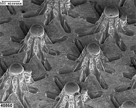
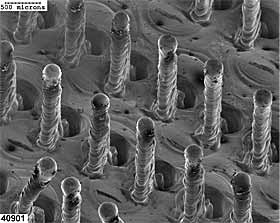
The most obvious effect of this technique is usually to form a series of protrusions (also known as proggles) above the original surface and usually corresponding intrusions, or holes, in the substrate. These protrusions and holes can be designed to be specific shapes and dimensions and the holes may even penetrate the workpiece altogether, giving burr-free perforations of controlled shape. Examples are shown in Fig.1.
 |
 |
|
Fig.1. Examples of Surfi-Sculpt
|
Surfi-Sculpt is a relatively rapid process as the features are usually formed in groups, rather than individually. In an area of 25mm by 25mm a group of several hundred features may be formed by a single beam in about ten seconds.
Initial studies, performed at TWI [5] investigated the use of Surfi-Sculpt to create a new technology, called Comeld, for joining composites to metals. This work demonstrated the feasibility of Comeld joint production and indicated the potential benefits of this joining system. Research continues at TWI to demonstrate the flexibility of the Comeld technique and the full range of benefits of the system. The current paper describes part of this research, focusing on tensile test data from different joint systems.
3. Joint manufacture
In order to demonstrate the flexibility of the Comeld technique, Comeld joints have been produced using different materials, different production techniques and different joint designs. Table 1 provides a description of the joints that were manufactured for the research presented in this paper, with joint dimensions provided in Fig.2.
Table 1 Description of joints manufactured
| Joint number | Metal | Composite | Manufacturing method |
|---|
| 1 |
Stainless steel 316L |
Glass fibre reinforced plastic (GFRP) from E-glass non-crimp fabric ELT-850 and EBX-602 with Reichhold Dion 9102 500 vinylester resin |
Vacuum infusion |
| 2 |
Titanium 6Al-4V |
Carbon fibre reinforced plastic (CFRP) from Hexply8552 prepreg with IM7 carbon fibre |
Autoclave |
Fig.2. Dimensions of double step joint
The steps taken to produce the Comeld joints were:
1. The metallic part of the joint was machined to the correct shape for the style of joint to be formed, as shown in Fig.3.
Fig.3. Metal machined to shape for a double step joint
2. An appropriate Surfi-Sculpt treatment was then applied to the joint section of the machined metal part as shown in Fig.4.
Fig.4. Surfi-Sculpt applied to joint section of metal
3. An appropriate additional surface treatment
[6] was applied to the joint section of the metal specimen to promote adhesion between the metal and the resin of the composite.
4. The composite material was laid-up onto the treated surface of the metal to form the joint shown in
Fig.2. The details of this process depended on the manufacturing process being used (vacuum infusion or prepreg/autoclave), but standard composite manufacturing guidelines were followed for each process.
5. The composite was cured according to the resin manufacturer's instructions, thereby consolidating the Comeld joint.
For each type of Comeld joint that was produced, control specimens were also produced. In these control specimens the Surfi-Sculpt process was replaced with grit blasting. The decision was taken not to include an adhesive in these control specimens as this would have necessitated significant differences in joint production method between the Comeld and control specimens for some of the joints produced, thereby making direct comparison difficult. Instead, the resin of the composite provided the adhesive bond between the composite and the metal. It is recognised that many of the joining techniques currently used include an additional adhesive layer and therefore adhesive comparisons are being performed as part of further research.
Examples of the Comeld and control joints produced are shown in Fig.5 - Fig.8. These pictures demonstrate that Comeld joints can be successfully produced without voids or defects using autoclave and vacuum infusion.
Fig.5. Comeld joint between stainless steel and GFRP (Joint 1 in Table 1)
Fig.6. Control joint between stainless steel and GFRP (Joint 1 in Table 1)
Fig.7. Comeld joint between titanium and CFRP (Joint 2 in Table 1)
Fig.8. Control joint between titanium and CFRP (Joint 2 in Table 1)
4. Tensile testing results and discussion
All Comeld and control joints were tested in tension at a cross-head displacement rate of 1mm/min, at room temperature and humidity. Load and cross-head displacement were recorded.
4.1 Joints between stainless steel and GFRP (joint 1)
The results of tensile testing of control and Comeld joints between stainless steel and GFRP are given in Tables 2 and 3 respectively. Representative load-displacement curves for the control and Comeld joints are also given in Fig.9. It can be seen that the Comeld specimens had a higher load carrying capability and exhibited a much greater extension before failure than the control specimens. On average, the Comeld specimens absorbed more than five times as much energy as the control specimens before failure.
Table 2 Results of tensile testing of control joints between stainless steel and GFRP.
| Specimen | Load/kN | Stress/MPa | Displacement/mm | Energy to Max Load/J |
|---|
| G-Con1 |
20.75 |
121.4 |
1.6 |
22.2 |
| G-Con2 |
18.94 |
111.7 |
1.4 |
17.6 |
| G-Con3 |
26.26 |
146.2 |
2.4 |
43.7 |
| G-Con4 |
20.26 |
117.9 |
1.6 |
21.5 |
| Av |
21.55 |
124.3 |
1.7 |
26.2 |
| STD |
3.23 |
15.1 |
0.5 |
11.8 |
Table 3 Results of tensile testing of Comeld joints between stainless steel and GFRP
| Specimen | Load /kN | Stress/MPa | Displacement/mm | Energy to Max Load/J |
|---|
| G-Com1 |
39.80 |
210.2 |
6.2 |
163.9 |
| G-Com2 |
36.96 |
204.3 |
4.9 |
120.1 |
| G-Com5 |
35.98 |
194.3 |
4.9 |
117.9 |
| G-Com6 |
37.81 |
191.2 |
5.3 |
135.1 |
| Av |
37.64 |
200.0 |
5.3 |
134.3 |
| STD |
1.63 |
8.8 |
0.6 |
21.2 |
The loading history for the control specimens and Comeld specimens ( Fig.9) was identical until the sudden failure of the control specimens. As shown in Fig.10, the failure of the control specimens occurred at the interface between the composite and the metal.
In the case of the Comeld specimens, whitening was seen at load values slightly below the failure load for the control specimens within the composite section of the joint near the end of the metal section (section 'A' in Fig.11). This whitening was matrix cracking within the composite. It is thought delamination of the composite prior to failure was prevented by the through thickness stitching of the non-crimp fabric. Instead, progression of damage in the form of matrix cracking was seen and heard until the failure point, when dramatic delamination was accompanied by fibre and matrix fracture.
Fig.9. Results of tensile testing of joints between stainless steel and GFRP
Fig.10. Failed control specimen between stainless steel and GFRP
Fig.11. Failed Comeld specimen between stainless steel and GFRP
4.2 Joints between titanium and CFRP
The results of all tensile testing on control and Comeld joints between titanium and CFRP are shown in Tables 4 and 5 and Fig.12.
Table 4 Tensile test results for control joints between titanium and CFRP.
| Specimen | Load/kN | Stress/MPa | Displacement/mm | Energy at Max Load/J |
|---|
| C-Con3 |
25.29 |
155.0 |
0.5 |
7.0 |
| C-Con4 |
19.41 |
117.9 |
0.4 |
3.6 |
| C-Con5 |
8.99 |
54.0 |
0.6 |
9.0 |
| C-Con6 |
14.40 |
86.8 |
0.3 |
2.1 |
| Av |
17.02 |
103.4 |
0.4 |
5.4 |
| STD |
6.96 |
43.2 |
0.1 |
3.2 |
Table 5 Tensile test results for Comeld joints between titanium and CFRP.
| Specimen | Load/kN | Stress/MPa | Displacement/mm | Energy at Max Load/J |
|---|
| C-M3 |
42.71 |
258.8 |
2.3 |
70.2 |
| C-M4 |
44.55 |
263.8 |
2.4 |
77.3 |
| C-M5 |
44.16 |
261.5 |
2.4 |
78.0 |
| C-M7 |
41.97 |
244.9 |
2.0 |
60.0 |
| Av |
43.35 |
257.3 |
2.2 |
71.4 |
| STD |
1.21 |
8.5 |
0.2 |
8.4 |
By comparing the test data for control and Comeld joints it can be seen that the Comeld joints outperformed the control joints in many ways. The Comeld specimens had a higher load bearing capability and exhibited considerably more extension during loading than the control specimens. Further examination also reveals that the standard deviation in the test results for the Comeld joints are significantly smaller than those for the control joints. This higher degree of consistency is potentially significant for designers who need to design joints between composites and metals since it provides confidence in the system which may allow a decrease in design allowables.
Fig.12. Tensile test data for control and Comeld joints between titanium and CFRP
Figure 12 shows data from one control joint and one Comeld joint. It can be seen that the two joints have similar loading characteristics initially although the Comeld joint continued carrying load long after failure of the control joint. After the 'knee' in the Comeld load displacement curve, which is thought to be a characteristic of the double step joint, three dips can be seen in the curve. These are depicted using the symbol A. These dips corresponded to damage, which was heard in the form of cracking and subsequently seen as delamination in the composite, initiating at the steps in the joint. It can be seen that despite the damage and dip in the curve, the joint continued to carry load.
Tables 4 and 5 and Fig.12 also demonstrate the exceptional energy absorption characteristics of Comeld joints when compared to control joints. The average values indicate that Comeld joints absorbed in excess of 13 times more energy before failure than the control joints.
The failure modes of the two types of joints were extremely different. The control joint shown in Fig.13 was observed to fail suddenly, without warning, at the interface between the composite and the metal. By contrast, damage was seen to initiate in the composite section of the Comeld specimen, shown in Fig.14, at the end of the titanium (area A). Cracks and delamination propagated through the composite, absorbing energy but without significantly affecting the load carrying capability. The second stage of damage initiated at the intersection of step 1 and step 2 in the titanium sample (areas B), again allowing cracks and delaminations to propagate through the composite. Final failure occurred with delamination of the composite and plastic deformation of the protrusions in step 2, designated 'C'. All of these damage mechanisms described absorbed energy and gave audible and visual signs that, in a real structure, would allow detection of a problem before failure.
Fig.13. Failed control joint between titanium and CFRP
Fig.14. Failed Comeld joint between titanium and CFRP
5. Summary
The results of tensile testing on Comeld specimens between stainless steel and GFRP demonstrated that, in comparison to control specimens they withstood loads 75% higher, the displacement before failure was three times higher and the energy absorbed was five times higher.
The crucial difference between these Comeld and control specimens was the failure mode. The control specimens failed without warning at the interface between the metal and the composite whereas the Comeld specimens prevented interfacial failure, initially exhibited damage without losing load-carrying capability and final failure occurred within the composite material.
Damage occurred in the Comeld specimens in the form of plastic deformation of the metal protrusions and matrix cracking and fibre damage within the composite. This damage contributed to the increase in energy absorbed before failure of the joint. It is thought that the through-thickness stitching in the non-crimp glass fabric prevented delamination, which might have occurred in alternative fabric forms.
Similarly, tensile testing of Comeld joints between titanium and CFRP demonstrated that, when compared to control joints, they were able to withstand loads more than two times greater, the displacement before failure was five times greater and the amount of energy absorbed was 13 times greater.
As with the previous materials system, the critical difference between the control and Comeld specimens was the failure mode. The control specimens failed without warning, at the interface between the composite and the metal. By contrast, the Comeld specimens prevented interfacial failure, exhibited damage, in the form of resin cracking and delamination that could be seen and heard but did not affect the load carrying capability, quite a long time before failure finally occurred in the composite material.
The fact that Comeld joints have been created that exhibit damage before failure, in some cases without affecting load carrying capability, could prove to be a useful tool to designers. It means that structural health monitoring could be built into a structure by designing a Comeld joint that initiates damage when loaded beyond its design load while incorporating sensors in the structure to perform in-service non-destructive testing. This will allow engineers to receive advance warning of a structure that has been loaded beyond its design load while preventing sudden failure.
The relatively high amount of energy absorbed by the damage initiated prior to failure in a Comeld joint also means the joining system has potential applications in structures that are required to withstand crash loading. The fact that the joints can retain integrity while absorbing energy means that they could be used to dissipate the energy of a crash whilst protecting the cargo contained within the structure.
The tensile data produced for Comeld joints between both materials combinations also produced relatively smaller standard deviation values than the data for control joints. This demonstrates a higher degree of consistency in the failure of Comeld joints than seen in the control joints, which has important implications for designers. Reduction in the scatter of test data associated with composites is crucial, since it is one way the very high safety factors currently imposed by designers on components containing composites could be reduced.
6. Conclusions
- Comeld joints between metals and composite materials have been successfully produced using both autoclave processing and vacuum infusion.
- Comeld joints demonstrate improved strength, displacement before failure and energy absorbing characteristics than control joints when subjected to tensile loading.
- Comeld joints can prevent sudden interfacial failure in joints between composites and metals.
- Comeld joints have been created that exhibit damage without loss of load carrying capability. These have potential for applications where structural health monitoring is required.
- Comeld joints demonstrate a higher degree of consistency in mechanical testing data than control joints.
7. Acknowledgements
The author would like to thank Anita Buxton and Bruce Dance of the Electron Beam section at TWI for the guidance and work provided as part of this research. Thanks also go to Alan Leong, Colin Langdown and Bill Godwin of the Materials Department at Queen Mary, University of London for their skills in composite manufacture.
8. References
- www.adhesivestoolkit.com/
- Hart-Smith L J: 'Adhesive bonded single lap joints'. NASA CR 112236. January 1973.
- Collings T A: 'Experimentally determined strength of mechanically fastened joints'. Joining fibre-reinforced plastics. Edited by F L Matthews. Elsevier Applied Science. 1987, pp.9 - 63. ISBN 1-85166-019-4.
- Dance BGI, Kellar EJC: 'Workpiece Structure Modification'. International Patent Publication Number WO 2004/028731 A1.
- Smith F: 'Comeld TM - An innovation in composite to metal joining.' Composites Processing 2004, CPA, Bromsgrove, UK, 23 April 2004.
www.composites-proc-assoc.co.uk/cpapapersabstract.php?pid=34
- www.adhesivestoolkit.com/Docu-Data/SurfacePreTreatment.xtp#ref7