J. Mawella
Defence Procurement Agency, Ministry of Defence, Abbeywood, Bristol BS34 8JH, UK
Paper presented at the 11th CF/DRDC International Meeting on Naval Applications of Materials Technology, held at Halifax (Nova Scotia, Canada) on 7-9 June 2005.
Abstract
In laser-arc hybrid welding, a welding arc and a laser beam converge in a single molten pool. The process thus allows some of the disadvantages of the separate processes to be overcome, such as the low tolerance to joint fit-up ofthe laser, and the limited penetration of the arc welding process. For these reasons, laser-arc hybrid welding is already applied in some industries, including shipbuilding, as well as being extensively researched in others. However,most research efforts and applications reported so far in the shipbuilding industry have concentrated on lower grade C-Mn and A-grade steels.
This paper describes the development of CO 2 laser-MAG hybrid welding for DH36, a higher-grade shipbuilding steel with a low temperature toughness requirement. Procedure development work is presented for butt welds in 5 and 8mm thickness, made with a 0.5mmjoint gap. The main variables were wire feed rate, travel speed, choice of lead process and laser focus position, the latter of which proved very influential. With the welding procedures developed, test panels were welded for full evaluation of the weld quality and static mechanical properties. This evaluation was performed to the Lloyd's Register Guidelines for the approval of CO 2 laser welding and other appropriate standards, and included visual and X-ray examination, hardness testing, and tensile, bend and Charpy impact testing.
1. Introduction
In laser-arc hybrid welding, a welding arc and a laser beam converge in a single molten pool. Many combinations are feasible (for example CO 2 , Nd:YAG or Yb fibre laser with plasma arc welding (PAW), tungsten inert gas welding (TIG/GTAW) or metal active gas welding (MAG/GMAW)), although laser in combination with MAG is the most widely applied. In sucha hybrid arrangement, some of the disadvantages of the separate processes can be overcome, such as the low tolerance to joint fit-up of the laser, and the limited penetration of the arc welding process.
Laser and laser-arc hybrid welding have already been employed for shipbuilding applications for some years in a few yards, particularly in Europe. Laser-arc hybrid welding -and then particularly CO 2 laser-MAG- is the more popular process, because it can cope better than laser welding with the joint fit-up accuracies typically achievable in shipyards. The justification for shipyards for investing in the equipment for and development of these welding processes lies in the increased accuracy that can be realised, mainly through reduced (thermal) distortion. Since rework needed for correction of inaccuracies and thermal distortion(mainly caused by welding processes) can amount to some 15-30% of the labour costs for new builds, [1-4] improved manufacturing accuracy can give considerable savings and a higher quality finished product.
Although the first CO 2 laser-MAG hybrid welding cells are now operational in shipyards, most shipbuilding applications, and indeed most research projects performed, have only been concerned with A- and AH-grade shipbuilding steels,the bulk steel used for most shipbuilding applications. However, for higher specification applications (for example Navy ships), higher-grade steels are generally used. The project described in this paper, therefore, was concerned with the development of hybrid welding procedures acceptable under classification society rules [6] for DH36, a higher-grade shipbuilding steel.
2. Experimental work
2.1 Materials
Two thicknesses of DH36 were of interest, namely 5mm and 8mm. DH36 is the designation for a Lloyd's Register of Shipping specified [5] higher-grade shipbuilding steel, in which 'H36' refers to a minimum specified yield strength of 355MPa, and 'D' to a minimum toughness requirement down to -20°C. The specified allowable chemical composition range can be found in Table 1. DH36 of 5mm in thickness was readily sourced (the composition can be found in Table 2). The material was coated with a Zn-based primer, which was removed from the weld zone by shotblasting. For the experiments in 8mm thickness, as there was difficulty in sourcing 8mm thickness DH36 within the timescale of the project, 12mm thickness DH36 was used with 2mm machined off either surface in the weld zone, to reduce the thickness to 8mm (chemical composition can be found in Table 2).
Table 1 Requirements for the chemical composition of DH36 steel. For full details, the reader is referred to reference [5] .
| Element | C | Mn | Si | S | P | Al | Nb | V | Cu | Cr | Ni | Mo |
|---|
| Fraction [%wt] |
0.18 max. |
0.90-1.60 |
0.10-0.50 |
0.040 max. |
0.040 max. |
0.015 min. |
0.015-0.05 |
0.05-0.10 |
0.35 |
0.20 |
0.40 |
0.08 |
Table 2 Chemical composition of the steels used in this project (concentration of the main elements, as determined by OES at TWI).
| Steel | %wt |
|---|
| C | Mn | Si | S | P | Al | Nb | V | Cu | Cr | Ni | Mo |
|---|
| S355J2G3 (5mm) |
0.16 |
1.39 |
0.37 |
0.012 |
0.010 |
0.035 |
- |
0.005 |
0.029 |
0.025 |
0.038 |
0.003 |
| S355J2G3 (8mm) |
0.14 |
1.49 |
0.37 |
0.006 |
0.016 |
0.043 |
- |
0.059 |
0.014 |
0.024 |
0.018 |
- |
| DH36 (5mm) |
0.15 |
1.36 |
0.35 |
0.010 |
0.009 |
0.036 |
0.003 |
0.005 |
0.026 |
0.026 |
0.038 |
0.004 |
| DH36 (12mm) |
0.12 |
1.28 |
0.28 |
0.008 |
0.013 |
0.036 |
0.024 |
0.001 |
0.010 |
0.012 |
0.020 |
- |
For both thicknesses, due to the limited availability of DH36 within the project, the bulk of the early procedure development work was performed on S355J2G3 steel (S355J2G3 is the structural, non-shipbuilding equivalent of DH36).The chemical composition of this steel can also be found in Table 2.
Copper-coated ESAB OK Autrod 12.51 solid MAG filler wire of 1mm diameter was used (consumable class A18/ER70S-6). This wire has Lloyd's Register approval as Consumable Grade 3YS, suitable for welding of DH36 steel, in combination with 80% Ar-20% CO 2 shielding gas. In the project, however, BOC Stainshield Universal (55% He-43% Ar-2% CO 2 ) was used as the MAG shielding gas. The main reason for this is that a high fraction of argon in the shielding gas during CO 2 laser welding tends to result in a dense plasma, absorbing and scattering the laser beam. The occurrence of such a plasma is also expected during CO 2 laser-MAG hybrid welding, particularly as the presence of the arc may further promote ionisation of the shielding gas. An experiment was performed with 80% Ar-20% CO 2 shielding gas, indeed confirming this to be the case.
2.2 Equipment
A Laser Ecosse AF8 fast axial flow CO 2 laser was used for all experiments. The beam was focused using a 250mm focal length parabolic mirror, giving an estimated focused spot size of 0.4mm in diameter. With the set-up at TWI, power levels of up to~6kW at the workpiece could be achieved.
A Fronius Time-twin master MAG power source was used with a push wire feeder and a straight-neck torch. A standard synergic welding programme was chosen (SG2/3, suitable for the filler wire and gas composition used). The welding torch was brought into close proximity to the molten pool using a specially manufactured bracket, allowing variation of key parameters such as process separation and torch angles. To allow the MAG shroud to be close to the molten pool without the laser beam clipping it, a slot was machined in the side of the MAG shroud to let the laser beam pass through. The workpiece was held in a simple butt-welding jig that was moved underneath the welding torches on an X-Ytable. For welding of the large test panels, a large base plate was used and the sample was bolted to it on both sides of the weld.
2.3 Experimental approach
First experiments were performed on the S355J2G3 steel, the structural equivalent to DH36. The samples for procedure development were typically made up of two plates of either 300mm or 250mm in length by 150mm wide. Sawn edges were used and the top surface of the plates was shot blasted in the weld region to remove rust. The plates were manually tacked at both ends in a square butt arrangement with, unless stated otherwise, a 0.5mm joint gap (considered a typical joint gap found in a shipyard). A bolt was manually welded onto one of the plates to provide a good contact for the arc welding current return lead. Welding was performed in the flat (PA) position. Welding procedure development was undertaken to make welds of the required penetration, and with acceptable external and cross-sectional appearance. For promising conditions, radiographic quality was also used as a criterion during the procedure development. For final procedure optimisation, as well as for welding of the actual panels for quality and property testing, DH36 steel was used. During this final procedure optimisation on DH36, weld zone hardness was also used as a development criterion.
When conditions had been optimised, test panels of 1000x500mm were welded, again with sawn edges. The plates were tacked at start, middle and finish, again with a 0.5mm joint gap, and a bolt was welded to the plate to provide a good contact for the arc welding current return lead. The plates were bolted to a base plate through clearance holes with 5 bolts (at 200mm intervals) on each side of, and 50mm away from, the joint line, to mimic the considerable downward clamping force as would be used in most shipyards. The welds were made perpendicular to the rolling direction in both thicknesses and welding was performed in the flat (PA) position. During the welding of the test panels, a stop and restart were incorporated, to evaluate the suitability of the procedure for coping with sudden equipment shutdowns, as might be experienced in a shipyard, where the lengths welded are typically up to 20m. No ramping down/up of power or travel speed, or weld overlap were used for this stop and restart.
The quality and properties of the welded panel were evaluated using the following tests:-
- Visual inspection of the weld cap and root over the full weld length.
- Radiography of the full weld length.
- Macrosections (transverse cross-sections near start and finish, and a longitudinal, mid-thickness cross-section at the location of an abrupt stop and restart).
- Hardness testing: on two samples (near the start and finish, respectively).
- Tensile testing: one transverse tensile test.
- Bend testing: one longitudinal face bend test, as well as a transverse root and a transverse face bend test.
- Charpy impact testing: three sets (of three samples each) of longitudinal Charpy V-notch impact tests were taken, with the notch located in the weld centre, HAZ and base material respectively. Sub-size Charpy samples were used (10x5mm), impact tested at -20°C.
All testing was performed following the Guidelines for the approval of CO 2 laser welding [6] and other appropriate standards. [7]
3. Results and discussion
3.1 Procedure development
3.1.1 Initial experiments
Procedure development was undertaken with a laser power of 5kW at the workpiece, and the laser beam vertical, i.e. perpendicular to the workpiece (welding in the flat (PA) position) and travel angle zero. Travel speed and wire feed rate were the first parameters adjusted to give welds of acceptable penetration and top bead shape. However, other important parameters that were investigated included (see also Figure 1):-
- Laser-arc (or longitudinal) process separation, i.e. the distance along the joint line between the impingement points of the two processes at the workpiece surface)
- Lead process (and thereby MAG push or pull angle)
- Focus position
- Arc current type (pulsed or constant)
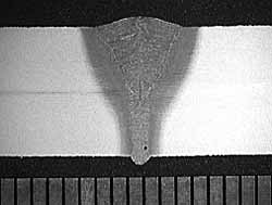
Of these, the process separation and focus position proved particularly important. The process separation influenced the stability of the metal transfer and welding conditions, and the cross-sectional shape of the weld.
Effect of variation of the laser focus position is shown graphically in Figure 2. The penetration increased as the laser focus position was taken further below the material surface. For example, at a focus position estimated to be -5mm, i.e. 5mm below the top surface of the sample, full penetration was achieved, whereas with the focus position at 0mm or -2mm, full penetration was not achieved for otherwise identical conditions. In these experiments, the most constant penetration bead was achieved with the focus position of the laser at -5mm. At that focus position, full penetration could also be achieved with a process separation of -1mm. A focus position of -5mm, together with zero longitudinal process separation, was used for the further procedure development work and welding of the 5mm and 8mm thickness test panels.
This result differs from what is generally experienced with autogenous laser welding, where when focus positions lie this far below the surface, penetration tends to decrease as the power density at the work piece surface decreases.Initially, as explanation was proposed the arc pressure depressing the weld pool surface to below the plate surface, bringing it closer to the laser focal plane. However, it is thought unlikely that the weld pool surface would be depressed this far. It may also be a combined effect of the arc pressure depressing the weld pool surface and the arc providing a molten surface, which increases the energy coupling with the laser beam. Therefore, at the molten pool surface, the defocused laser has enough power density to vaporise the steel and form a keyhole. The actual focus position then would lie in the laser keyhole, possibly further aiding penetration.
3.1.2 Procedure development and welding and testing of panel in 8mm thickness DH36
From the initial experiments, conditions were chosen for further procedure optimisation as required, initially still on 8mm thickness S355J2G3 steel. Development criteria were penetration, top bead and underbead size and quality,weld bead shape and radiographic quality.
The conditions considered optimised were as follows:-
These conditions were then verified on DH36, machined to 8mm thickness from 12mm. At this stage, the weld zone hardness was also measured, and found to be acceptable with the highest value being 323HV5, located in the HAZ. (Because the process is considered a low-hydrogen process, hardness values up to 380HV5 are allowed, with one value per traverse up to 400HV5.) [6]
|
|
0.5mm. |
|
|
1m/min |
|
|
5kW at workpiece |
|
|
-5mm |
|
|
90° (perpendicular to workpiece surface) |
- Longitudinal process separation:
|
0mm |
|
|
35° off vertical, pushing |
|
|
6.5m/min |
|
|
Pulsed current, standard programme (SG2/3) |
|
|
Stainshield Universal, 15 l/min |
Transverse cross-sections of welds made with these conditions in the S355 and DH36 are shown in
Figure 3. These conditions were also used for welding the 1m long test panel for further testing.
 a) 8mm thickness S355J2G3 steel and a) 8mm thickness S355J2G3 steel and
|
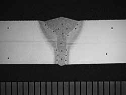 b) 8mm (machined down from 12mm) thickness DH36 steel (with hardness indents). Scale bars in millimetres b) 8mm (machined down from 12mm) thickness DH36 steel (with hardness indents). Scale bars in millimetres |
| Fig.3. Transverse cross-sections of welds made with the optimised welding procedure in |
The 1m long panel was then non-destructively and destructively tested. The welding procedure gave a very smooth, spatter-free weld with no significant defects, and was visually acceptable in accordance with BS EN ISO 13919-1:1997Level B.7 Constant penetration was achieved all along the weld, even at the location of the stop/restart and the middle shim and tack. The top bead profile was positive at the weld start, and mainly flat for the remainder of the weld,which was thought to be caused by the opening up of the set joint gap. The radiographs were mostly clear, showing isolated pores with a maximum diameter of approximately 0.5mm, one located at the stop/restart location. The radiographs were therefore acceptable to the requirements of BS EN ISO 13919-1:1997 Level B.7
A longitudinal, mid-thickness cross-section around the stop/restart position showed a continuous weld with a slight widening at the stop/restart position but no (crater) cracks or lack of penetration/fusion. None of the cross-sections showed significant defects. The hardness measurements gave the highest hardness of 317HV5 in the HAZ near the weld toes on both transverse cross-sections. The maximum weld metal hardness was 306HV5 at the start, and296HV5 at the end of the weld, below the maximum acceptable hardness of 380HV5.
The transverse tensile test gave parent material failure with a UTS of 532N/mm 2 and was thus acceptable (acceptable range [5] 490-620MPa). The face and root transverse and the face longitudinal bend tests gave no visible defects, and were therefore acceptable. The Charpy impact energies at -20°C for the sub-size Charpies (10x5mm) were acceptable for both the weld centre line and the HAZ at averages of 92 and 72J respectively (the parent material gave a Charpy impact value of 79J). Fracture path deviation occurred in both weld metal and HAZ samples.
The test results are also summarised in Table 3.
Table 3 Results of quality and properties tests for laser-arc hybrid welded 8mm thickness DH36
| Test | Acceptance criteria/standard | Results | Accept |
|---|
| Visual inspection. |
BS EN ISO 13919 Level C [7] (Laser Guidelines [6] ). |
No significant defects visible. |
Yes |
| Radiography. |
BS EN ISO 13919 Level C [7] (Laser Guidelines [6] ). |
No significant defects visible. |
Yes |
| Transverse cross-sections (macros) taken near weld start and end. |
Laser Guidelines. [6] |
Both show acceptable shape, adequate fusion and penetration with no significant defects visible. |
Yes |
| Longitudinal mid-thickness section, taken at position of sudden stop/restart parallel to plate surface. |
Laser Guidelines. [6] |
Weld shows adequate fusion. No significant defects visible. |
Yes |
| Hardness testing. |
380HV5 max. with one value up to 400HV5 (Laser Guidelines [6] ). |
Highest hardness 317HV5 (in HAZ) both near weld start and end. |
Yes |
| Transverse tensile test. |
490-620MPa Ultimate Tensile Strength (UTS) (Laser Guidelines [6] ). |
UTS of 532MPa with parent metal failure. |
Yes |
| Transverse face & root bend test and longitudinal face bend test. |
No surface imperfections >3mm in length (Laser Guidelines [6] ) |
No defects visible after 120° bend. |
Yes |
| Transverse Charpy V-notch impact testing (sub-size 10x5mm samples). |
2/3rds of 47J = 31J (Lloyd's Register). |
Average values of 92J (weld metal), 72J (HAZ) and 79J (parent). All samples for weld metal and HAZ exhibited fracture patch deviation. |
Yes |
3.1.3 Procedure development and welding of test panel in 5mm thickness DH36
In order to facilitate easy change-over between different thicknesses in a shipyard, it was decided not to change any of the parameters relating to the orientation of the torches unless absolutely necessary. Therefore, it was decided to keep the focus position fixed at -5mm, if possible, and zero longitudinal process separation with the arc pushing. This in effect meant that the focal plane of the laser beam was located at the bottom surface of the plates.
In the case of the 5mm thickness steels, welds were made with a good shape, that is fully penetrating with a triangular, smooth cap on top of a narrow laser root, and these could be achieved at travel speeds of around 2m/min. At these speeds, the welds looked very similar in shape to those achieved in the 8mm thickness steels, as can be seen from the transverse cross-section in Figure 4.
However, with the higher travel speed, a higher cooling rate resulted, causing excessive (i.e. >380HV5) [6] hardness in the weld zone. To combat this problem without changing the material, the heat input had to be increased which was achieved via a decrease in travel speed. However, although the wire feed rate and laser power had to be decreased together with the travel speed to maintain an acceptable weld bead shape and size, the reduction in travel speed and wire feed rate was sufficient to reduce the weld zone hardness to acceptable levels. The conditions thus used for welding of the 1m long test panel were as follows:-
|
|
0.5mm |
|
|
0.9m/min |
|
|
3.5kW at workpiece |
|
|
-5mm |
|
|
90° (perpendicular to workpiece surface) |
- Longitudinal process separation:
|
0mm |
|
|
35° off vertical, pushing |
|
|
4m/min |
|
|
Pulsed current, standard programme |
|
|
Stainshield Universal, 15 l/min |
A weld made at these conditions can be seen in Figure 5.
The weld on the test panel was smooth and exhibited full penetration all along its length, including at the sudden stop/restart location and middle shim and tack. The weld bead top profile was positive at the start of the weld,changing to flat and slight underfill (<0.5mm) further along the weld length, again thought to be caused by the opening up of the joint gap. Radiographic examination revealed some zones with many scattered, small pores. These were thought to be present in the weld cap, resulting from inadequate shielding. However, as the pores were very small (typically less than 0.2mm in diameter), the porosity was confirmed as acceptable, and it was not found to have an influence on the properties of the welded panel.
The transverse cross-sections confirmed the top bead surface to be slightly positive near the weld start, and flat with slight underfill near the end. However, the underfill was less than 0.5mm in depth and, therefore, within acceptable limits. [6-7] None of the cross-sections showed significant defects. The hardness measurements showed the highest hardness to be 381HV5 in the HAZ on the cross-section taken near the weld end and 332HV5 in the HAZ near the weld start. Although one value in excess of 380HV5 was found, it was under 400HV5 and therefore acceptable. [6] The maximum weld metal hardness was 306HV5 at the start, and 325HV5 at the end of the weld, and also acceptable. The transverse tensile test gave parent material failure with a UTS of 542N/mm 2 , and was acceptable. [6] The face and root transverse and the face longitudinal bend tests gave no visible defects. Both tests were acceptable.
All the test results are summarised in Table 4.
Table 4 Results of quality and properties tests for laser-arc hybrid welded 5mm thickness DH36
| Test | Acceptance criteria/standard | Results | Accept |
|---|
| Visual inspection. |
BS EN ISO 13919 Level C [7] (Laser Guidelines [6] ). |
No significant defects visible. Slight underfill near the weld end. |
Yes |
| Radiography. |
BS EN ISO 13919 Level C [7] (Laser Guidelines [6] ). |
No significant defects visible. Some areas with clustered, very small (<0.2mm) diameter pores. |
Yes |
| Transverse cross-sections (macros) taken near weld start and end. |
Laser Guidelines. [6] |
Slight underfilling evident near weld toes at start. Incompletely filled groove near weld end (<0.5mm in depth, therefore just acceptable). |
Yes |
| Longitudinal mid-thickness section, taken at position of sudden stop/restart parallel to plate surface. |
Laser Guidelines. [6] |
Weld shows adequate fusion. No significant defects visible. |
Yes |
| Hardness testing. |
380HV5 max. with one value up to 400HV5 (Laser Guidelines6). |
Highest hardness 332HV5 in HAZ near weld start and 381HV5 near weld end (only one indentation >380HV5 but <400HV5). |
Yes |
| Transverse tensile test. |
490-620MPa Ultimate Tensile Strength (UTS) (Laser Guidelines6). |
UTS of 542MPa with parent metal failure. |
Yes |
| Transverse face & root bend test and longitudinal face bend test. |
No surface imperfections >3mm in length (Laser Guidelines6). |
No defects visible after 120° bend. |
Yes |
4. Conclusions
Procedure development for CO2 laser-MAG hybrid welding was undertaken for DH36 shipbuilding steel in 5mm and 8mm thickness. Once procedures were optimised, 1m long test panels were welded for quality and mechanical property evaluation.
From the work, the following conclusions could be drawn:
- Successful CO2 laser-MAG hybrid welding procedures giving acceptable weld quality and properties have been developed for butt welds in 8mm and 5mm thickness DH36 steel with a joint gap of 0.5mm.
- The focus position of the laser beam proved to be an influential parameter, with penetration most consistent at an estimated position of the focal plane of -5mm (i.e. 5mm below the top surface of the material).
- When welding the 1m long test panels, both for the 5mm and 8mm thickness materials, opening up of the set joint gap appeared to occur towards the weld end, leading to flattening of the top bead, and -in the case of the 5mm thickness material- to slight underfilling (<0.5mm in depth). In industrial applications, this might be overcome by more frequent or heavier tacking and/or better jigging.
- The 5mm thickness DH36, which had a carbon equivalent value of 0.39, when welded at a travel speed of up to 2m/min, gave good penetration and weld profile, yet excessive hardness levels. As a result, the travel speed had to be reduced to 0.9m/min to reduce the cooling rate and thereby weld zone hardness.
5. Ongoing work
Currently, a second project on CO2 laser-MAG hybrid welding for the MoD is ongoing at TWI, again for DH36 shipbuilding steel. It includes fatigue testing for both butt welds and T joints.
Acknowledgements
This project benefited from the involvement of Dr David Howarth of Lloyd's Register of Shipping, UK, who provided advice, and Mr Norman McPherson of BAE SYSTEMS, UK, who provided material.
References
- G. Sepold and P. Seyffarth, 'Laserstrahltechnologien für den Schiffbau (Laser beam technologies for shipbuilding)', Proc. Conf. Schweissen und Schneiden 1994, DVS Berichte 162, 159-164, Bremen, Germany, 28-30 September 1994.
- M. Sellerup, 'Experiences of laser welding and cutting in hull production', Proc. Int. Inst. of Welding on Welding in Shipbuilding, DVS Berichte 195, 25-27, Hamburg, Germany, 17-18 September 1998.
- Anon., 'Brochure: Laser beam welding and cutting at Blohm+Voss GmbH', Blohm+Voss, Hamburg, Germany.
- P. Seyffarth, 'The use of high-power-lasers in shipbuilding', Proc. Int. Conf. Advanced Metallic Materials and their Joining, Bratislava, Slovakia, 25-27 October 2004.
- 'Rules and regulations for the classification of ships', Part 2: Rules for the manufacture, testing and certification of materials, Lloyd's Register of Shipping, July 2004.
- 'Guidelines for the approval of CO 2 -laser welding.' Lloyd's Register of Shipping, March 1997.
- BS EN ISO 13919-1:1997: 'Welding - Electron beam and laser welded joints - Guidance on quality levels for imperfections. Part 1: Steel', 1997.