D J Abson and H G Pisarski
Paper presented at Proceedings of OMAE-FPSO 2004, OMAE Specialty Symposium on FPSO Integrity, Houston, USA, 30 Aug - 2 Sept 2004.
Abstract
If repair to the underside of an FPSO becomes necessary, economic considerations require that, if at all possible, repair be carried out with the FPSO remaining on station. Any repair of defects in the bottom of an FPSO must therefore be effected underwater. The preferred approach is to attach an enclosed dam to the underside of the vessel, pump out the water and then complete the repair from the inside. However, where the risk of fire or explosion orballast considerations require, it may be necessary to complete the welded repair from inside the vessel by wet underwater welding.
This paper describes how weld repairs can be effected by the attachment of such a dam, and grinding, to simulate the removal and welded repair of a through-wall fatigue crack by wet underwater welding. The integrity and mechanical properties of these welds are discussed.
Introduction
In view of the interruption to supply that would accompany taking an FPSO off-station, and moving it to a dry dock, a repair will normally be carried out with the vessel on-station. For a repair to the bottom of an FPSO, the preferred approach will generally be to attach an enclosed dam to the underside of the vessel, drain it from inside, so that the damaged region can be repaired in the dry, prior to removing the dam. Where circumstances permit, the repair from the inside can be effected by welding in air. However, for safety or ballast considerations, it may be necessary to carry out the repair by welding under water from inside the hull.
This paper describes a demonstration of single-sided repair, appropriate to a repair following gouging and grinding to remove a through-wall crack in the bottom of an FPSO. The repair welds were made both by welding in air and bywet underwater welding. The paper also considers their inspection and mechanical testing. Also included is a demonstration of the attachment of an enclosed dam to the underside of a plate that simulated the bottom of an FPSO. In this case, a butt weld was deposited, simulating the repair of a gouged through-thickness crack.
Experimental approach
Parent Steels
The 20mm thick steel plate met the requirements of DNV 27S and LRS Grade D. This plate will be referred to as 'ship plate' in this paper. Parallel to the rolling direction, it had a yield strength of 293MPa and tensile strength of458MPa. An additional 20mm thick plate, to ASTM A516 Grade I, was also used. The chemical composition of these plates is given in Table 1.
Table 1 Chemical analysis of the parent steels and backing bars
| Identity | Element, wt% |
|---|
| C | Si | Mn | P | S | Cr | Mo | Ni | Al | Cu | Nb | Ti | V |
|---|
| Ship plate DNV 27S |
0.15 |
0.21 |
0.96 |
0.019 |
0.006 |
0.018 |
<0.004 |
0.021 |
0.033 |
0.010 |
≤0.002 |
0.001 |
≤0.002 |
| A516 grade 65 |
0.16 |
0.29 |
1.10 |
0.016 |
<0.002 |
0.030 |
<0.005 |
0.030 |
0.034 |
0.005 |
0.014 |
0.009 |
<0.002 |
| BS EN 10025 S275 JR |
0.18 |
0.23 |
0.59 |
0.010 |
0.030 |
0.051 |
0.005 |
0.042 |
0.010 |
0.065 |
<0.002 |
0.001 |
<0.001 |
| Mild steel |
0.05 |
0.11 |
0.41 |
0.015 |
0.032 |
0.080 |
0.017 |
0.091 |
<0.003 |
0.24 |
<0.002 |
0.001 |
<0.001 |
The A516 plate was also used to simulate the bottom of an FPSO in an exercise to attach an enclosed dam underwater to its underside. A simple 'dam' was fabricated from 460mm diameter API 5L X65 steel pipe, that was closed at one end with a disc of steel of similar strength. A flange, 15mm thick, was flame-cut and then welded in place so that it left a rim approximately 30mm wide on the outside. Four screw dogs were also fabricated, by cutting out L-shaped pieces of steel plate, each from a plate approximately 150 x 175 x 15mm, and welding M16 nuts down one edge, with a bolt threaded through them; the deployment of these screw dogs is discussed in the section on wet underwater welding.
Preparation of panels for welding
Two 'composite' butt weld panels were assembled with the ship plate constituting one side of the panel, and the ASTM A516 Grade 65 steel, for the opposite side; one of these was destined for welding in air, and the other for wet underwater welding. A further panel, 600mm long, was welded entirely in ASTM A516 Grade 65. In order to reduce distortion during welding, an end bar was welded to each end of both of the composite panels, and strong-backs were welded on to the panels that were welded in air.
Grooves were air carbon arc gouged and ground in the three panels. A U-groove with a root gap of approximately 4mm and an included angle of 50 ±10 degrees was prepared for the panel that was to be welded in air with an open root. The groove length was approximately 375mm long in the root, and approximately 475mm long at the 'cap' side. A further panel was prepared with the same preparation, except that the root gap was opened up to 8mm, and a backing bar was introduced. The backing strip was 12.5mm wide and approximately 3.5mm thick; it was held in place by wires that were threaded through predrilled holes, and tied to temporary supports that straddled the groove. The chemical composition of this backing bar is given in Table 1.
The preparation employed for the panel destined for wet underwater welding was a V-groove, with an included angle of approximately 30 degrees, and a root gap of approximately 10mm. The groove length was again approximately 375mmlong in the root, and approximately 475mm long at the 'cap' side. A backing bar was prepared from 25mm wide, 6mm thick mild steel, supplied to BS EN 10025 S275JR, Table 1; it was introduced from the 'cap' side of the weld, and held in place by wire loops passed through predrilled holes and then through washers that straddled the groove, and nuts; the wires were then tightened by twisting the nuts. (This preparation was done before the panel was inserted into the welding tank, but could have been carried out underwater.)
Welding in Air
A summary of all the welds is given in Table 2. All welding was carried out in the flat position. The U-groove in the composite panel, W02, was welded with an open root. The heat input values for the TIG root and hot pass, deposited with BS 2901 Part 1; 1983 A18wire, were 1.4 and 2.0 kJ/mm. The heat input for the third and fourth passes, deposited with 3.2mm diameter Eland 7018 MMA electrodes, and for the remaining passes with 4mm diameter Elga PSI 7018 MMA electrodes, was between 1.2 and 1.5kJ/mm. Welding was carried out without preheat.
Table 2 Summary of welds
| Identity | Configuration | Consumable used for root and hot pass | Consumable used for fill and cap |
|---|
| W01 |
V-groove |
Hydroweld FS |
Hydroweld FS |
| W02 |
U-groove |
A18 TIG rod |
3.2mm Eland 7018 & 4mm diameter
Elga P51 7018 |
| W03 |
U-groove |
3.2mm Eland 7018 & 4mm diameter
Elga P51 7018 |
4mm diameter Elga P51 7018 |
| W04 |
3-pass fillet |
Hydroweld FS |
Hydroweld FS |
For the gouged and ground groove in weld W03, the root pass was deposited against a backing bar using 3.2mm diameter Eland 7018 MMA electrodes; the heat input was 1.3kJ/mm. For the remaining passes, deposited with 4mm diameter ElgaPSI 7018 MMA electrodes, the heat input was in the range 1.3 to 1.5kJ/mm. Again, no preheating was employed.
Wet Underwater Welding
The electrodes used for the wet underwater weld, W01, were 3.2mm diameter Hydroweld FS electrodes. All welding was carried out in a flat position, except that the fillet welding to attach the screw dogs to the underside of the plate was carried out overhead.
Two exercises were carried out. The first exercise consisted of a simple demonstration of the attachment of an enclosed dam to the underside of a plate underwater, simulating the attachment of such a structure to the underside of an FPSO. A gasket cut from closed cell polymer foam was adhesively bonded to the welded flange of the enclosed dam; see Fig.1. The attachment of the dam was effected by welding each of four screw dogs to a flat plate, representing the hull, with a three-pass fillet weld. The screw dogs were arranged radially, such that each bolt impinged on the flange of the enclosed dam. Whilst a flotation device would normally be used in practice, it was not employed in this instance. Instead, the enclosed dam was supported from above, through a hole cut in the centre of the plate to which it was being attached, thereby simplifying positioning of the assembly underwater. However, in other respects the activity was a simulation of the attachment of an enclosed dam.
Fig.1. Enclosed dam attached to the plate that simulated the bottom of the hull of an FPSO. Each of the four screw dogs shown was attached by depositing a three-pass fillet weld on one side in the overhead position.
The second exercise consisted of depositing a butt weld, W01, in the prepared V-groove, in the flat position.
A separate piece of the plate from which the screw dogs were cut was similarly fillet welded on to the ship plate, so that HAZ hardness could be measured. (This welding was actually carried out in the flat position, rather than overhead.)
Examination and Testing
The panels were examined visually, radiographed, and examined ultrasonically, using P-scan, with both 60 and 70 degree probes, to generate a three-dimensional representation of any defects present.
Following visual examination and NDE, the panels were sectioned, as required in BS EN 288:Part 3 [1] . Samples for metallographic examination, chemical analysis and mechanical testing were prepared. These included cross-weld tensile, hardness and fracture toughness tests. Transverse weld tensile specimens were machined and tested according to BS EN895:1995 [2] . Fracture toughness specimens were prepared and tested in accordance with BS 7448: Parts 1 and 2 [3, 4] . These were all notched in the through-thickness direction, (NP direction according to BS 7448:Part 2). Specimens were notched along the weld centre line, and in the HAZ (with the notch intersecting the weld fusion boundary at mid-thickness). The primary rolling direction in the Grade 'A' ship plate, which contained the test HAZ, was parallel to the welding direction (BS 7448:Part 2 crack plane orientation N x P).
After notching, the ligament below the notch was locally compressed, in accordance with BS 7448:Part 2 [4] , in order to reduce residual stresses to low and uniform levels, and so promote the growth of straight fatigue cracks.
The specimens were instrumented with a double clip gauge arrangement, in order to estimate crack mouth opening displacement (CMOD). This arrangement enabled CTOD and J to be estimated in accordance with the BS 7448:Parts 1 and 2,and also J to be estimated from CMOD. The equations for estimating J from CMOD are given in Ref. [7] .
The fracture toughness tests were conducted according to the requirements of BS 7448:Parts 1 and 2 [3, 4] at 0°C; this is intended to represent a typical minimum sea water temperature.
Results
Welding in Air
Welding proceeded satisfactorily, with no serious problems being encountered, except for slight burn-through of the 3.5mm thick backing bar, which indicates that the use of a slightly thicker backing bar is preferable.
Wet Underwater Welding
Deposition of the wet underwater weld, W01, proceeded smoothly, with no major problems, and with only occasional grinding, particularly of weld finish regions, being required. The welder diver generally has only limited scope for varying the heat input. The reported range of heat input values was from approximately 1.5 to 1.8 kJ/mm. Short lengths of tack weld in the root, that joined the backing bars to the panels, prior to removal of the wires supporting the backing bar, were blended into the root weld beads.
Similarly, the deposition overhead of the four three-pass fillet welds to attach the screw dogs did not give any welding problems. For each of the welds, the first pass was deposited at a heat input of approximately 2.5kJ/mm, and the two subsequent passes at a heat input of approximately 1.2kJ/mm.
Visual Appearance of the Panels
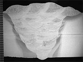
Photographs of two of the butt welded panels are shown in Fig.2 and 3. The visual appearance of all the welds, including W01 deposited underwater, was good, as expected for MMA welds deposited in the flat position.
Fig.2. Weld W02, deposited in air, with an open root
Fig.3. Weld W01, deposited under water employing a backing bar
X-Radiography
W01, the wet underwater weld, met the radiographic requirements of AWS D3.6 [5] Class A, which is the quality that is required of welds deposited in air. Welds W02 and W03 contained no significant defects, and were acceptable to BS EN 25817:1992 [6] Level B.
Ultrasonic Testing
The P-scan images of the three butt welds were obtained using a 70 degree probe. The 60 degree probe picked up spurious images from the backing bar for welds W01 and W02. The interface between the two parts of the composite panel, beyond the end of the weld, was picked up for welds W01 and W02, and the edges of the backing bar were detected in weld W01. For the latter, two indications, that were 6 and 28mm long, respectively, were found in the root of W01. These root features were investigated by metallographic sectioning through the appropriate location.
Chemical Analysis
Weld metal chemical analyses, Table 3, show the expected leaner composition, and a normal comparatively high oxygen level, for the wet underwater weld, W01.
Table 3 Chemical analysis of welds W01 (wet underwater weld) and W02 (welded in air)
| Identity | Element, wt% |
|---|
| C | Si | Mn | P | S | Cr | Mo | Ni | Al | Cu | Nb | Ti | V | N | O |
|---|
| W01 |
0.082 |
0.32 |
0.43 |
0.023 |
0.007 |
0.024 |
0.004 |
0.036 |
<0.003 |
0.018 |
0.004 |
0.012 |
0.011 |
0.0067 |
0.100 |
| W02 |
0.053 |
0.55 |
0.99 |
0.010 |
0.050 |
0.050 |
0.027 |
0.047 |
0.010 |
0.013 |
0.003 |
0.025 |
0.016 |
- |
- |
Metallographic Examination
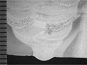
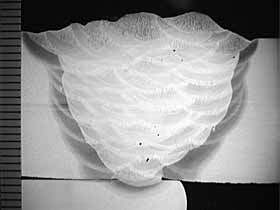
Photomacrographs of two of the three butt-welds are shown in Fig.4(a), and 5(a). The generally good profile of all the welds is noted, particularly that of the TIG root bead that was deposited in the open root of weld W02, Fig.4(b).
| 4a) Overall view |
4b) Root Detail |
 |
 |
| Fig.4. Transverse section through weld W02. The nominal magnification is indicated by the millimeter scale |
| 5a) Overall view |
5b) Root detail, showing a small crack in the weld metal |
|
 |
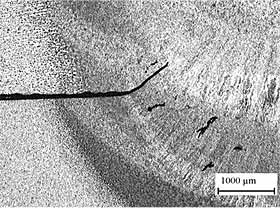 |
| Fig.5. Transverse section through weld W01. The nominal magnifications are indicated by the millimeter scale and by the micron bar. |
he features detected by ultrasonic testing at two locations along weld W01 were investigated by metallographic sectioning, which revealed, in each case, a shallow crack in the weld root, approximately 1mm deep. One of these features is shown in
Fig.5(b).
The section through the three-pass weld, simulating the weld that attached the screw dog plate to the ship plate revealed adequate penetration on both legs of the fillet weld, but some undercut in the weld that impinges on the screwdog plate. However, this is of little consequence, as such welds are intended as temporary attachments, and the weld in these trials was deposited solely to permit measurement of HAZ hardness in the underlying plate.
Cross-Weld Tensile Tests
The cross-weld tensile tests revealed that fracture occurred in the ship plate parent steel, with a tensile strength of > 475MPa. This is just above the ultimate tensile strength determined for this material (458MPa).
Hardness Tests
The Vickers hardness test results, reported in Table 4, reveal that mean weld metal hardness for the butt-welds ranged from 173HV10 to 220HV10. Mean hardness values for the ship plate showed some variability, with a range of 154HV10 to 174HV10. Maximum HAZ hardness values in this plate ranged from 177HV10 to 207HV10 for weld W02, deposited in air, and from 215HV10 to 336HV10 for weld W01, deposited underwater.
Table 4 Vickers hardness data
| Identity | Parent steel
Ship plate
 | HAZ in
Ship plate
|
Weld metal
| HAZ in
A516 grade 65
| Parent steel
A516 grade 65
|
|---|
| W01 cap |
 |
 |
 |
 |
 |
| W01 root |
 |
 |
 |
 |
 |
| W02 cap |
 |
 |
 |
 |
 |
| W02 root |
 |
 |
 |
 |
 |
| W04 'cap' |
 |
 |
 |
- |
- |
| W04 'root' |
 |
 |
 |
- |
- |
The cap and root mean weld metal hardness values for the three-pass underwater fillet weld, W04, were 173 HV10 and 220HV10, respectively, which is a little higher than for the butt weld deposited underwater, possibly reflecting a faster cooling rate. Parent steel mean hardness values were surprisingly low at 134HV10, while the maximum HAZ hardness was 345HV10, which is marginally higher than the maximum value for the wet underwater butt-weld.
Fracture Toughness Tests
The fracture toughness test results are summarised in Table 5. Since the weld metal yield strength was not determined, an estimated room temperature yield strength of 390MPa was calculated from the hardness results given in Table 4, using an equation given in BS 7448:Part 2 [4] . The weld metal overmatched the yield strength of the parent plate by about 33%.
Table 5 Fracture toughness results on weld metal and HAZ at 0°C
| Notch location | Specimen No | CTOD (1)
mm | Type of result | J CMOD, (2)
N/mm |
|---|
| Wet underwater V-weld, weld metal |
W01-1 |
0.085 |
δ m |
67.8 |
| Wet underwater V-weld, weld metal |
W01-2 |
0.104 |
δ m |
83.7 |
| Wet underwater V-weld, weld metal |
W01-3 |
0.086 |
δ m |
66.2 |
| Wet underwater V-weld, HAZ |
W01-4 |
0.093 |
δ m |
70.4 |
| Wet underwater V-weld, HAZ |
W01-5 |
0.100 |
δ m |
76.8 |
| Wet underwater V-weld, HAZ |
W01-6 |
0.142 |
δ m |
116.5 |
| U-weld made in air, weld metal |
W02-1 |
0.438 |
δ u |
415.3 |
| U-weld made in air, weld metal |
W02-2 |
0.258 |
δ c |
275.9 |
| U-weld made in air, weld metal |
W02-3 |
0.734 |
δ m |
711.7 |
| U-weld made in air, HAZ |
W02-4 |
0.401 |
δ m |
346.1 |
| U-weld made in air, HAZ |
W02-5 |
0.385 |
δ m |
332.6 |
| U-weld made in air, HAZ |
W02-6 |
0.418 |
δ m |
359.0 |
Notes:
(1) CTOD estimated according to BS 7448:Parts 1 and 2 [3, 4]
(2) J estimated from CMOD according to Ref [7] |
The CTOD results for the HAZ in the ship plate tend to reflect the trends observed in the weld metal tests. Namely, lower values (in the range 0.093 to 0.142mm) were obtained from the underwater weld W01 compared with the weld made in air, W02 (where the CTOD values were in the range 0.385 to 0.418mm). None of the specimens fractured by cleavage, and all gave maximum load behaviour ( δm). Given that in welds W01 and W02 the line of the notch in the test specimens contains HAZs made in the same parent plate, made at similar heat inputs and the weld metal hardness/estimated yield strengths were the same, the CTOD values would be expected to be similar. The difference is attributed to the way the HAZ fracture toughness specimens were notched. The HAZ was intersected at mid-thickness, so that approximately half the front was in weld metal. It is therefore likely that the CTOD values are dominated by the fracture behaviour of the weld metal. This means that in these welds, fracture behaviour of the joint is controlled by the weld metal rather than the HAZ.
Estimates of fracture toughness based on J reflect CTOD performance.
Discussion
A satisfactory approach for the repair of a fatigue crack in the bottom of the hull of an FPSO has been demonstrated. The attachment of the enclosed dam to the underside of a plate underwater provided a simple demonstration of the approach adopted prior to removal of a crack or damaged material in the bottom of the hull of an FPSO. The closed cell polymer gasket was used to provide a seal against the uneven bottom of a hull. In a real repair situation, a perforation would be made in the FPSO hull into the region enclosed by the dam, and the space drained and dried, if appropriate. The repair region would be excavated, and the repair effected from inside the vessel. In addition, upon completion of the repair, the screw dogs would be broken off, the residual parts of the attachment fillet welds ground flush with the bottom of the FPSO, and freedom from defects established by non-destructive examination. The check carried out on the HAZ hardness of the weld attaching the screw dog plate to the ship plate revealed a satisfactory level of hardness.
The wet underwater weld, deposited in the flat position, simulated the repair of a fatigue crack, the removal of which (by gouging and grinding to create a V-groove) was simulated. The groove had a root gap that was closed attaching a backing bar to the under-side. The exercise proceeded satisfactorily, giving a weld of good integrity, with only minor defects in the root. In practice, such defects would have been detected by inspection after grinding to remove the backing bar, and removed by further grinding. It should be noted that the quality of weld achieved, which met the AWS D 3.6 Class A inspection requirements, was of appreciably higher quality than would have been achieved if a weld had been attempted in the overhead position from below the hull of the vessel.
Of the two welds deposited in air, the preferred approach for the root pass was to deposit the bead by TIG welding, without a backing bar. The weld deposited using this procedure was subjected to the more detailed examination and testing.
The fracture toughness results indicate that at 0°C the fracture performance of both the wet underwater weld and the weld made in air is controlled by the fracture behaviour of the weld metal rather than the HAZ in the ship plate. In this particular case, the fracture toughness of the HAZ is not considered to be limiting. The apparently low HAZ fracture toughness values recorded for the wet underwater weld are considered to reflect the toughness of the weld metal rather than the HAZ, as approximately half the crack front was located in weld metal. Thus, the fracture toughness of the HAZ is expected to be higher than the weld metal.
The observation that HAZ fracture toughness is not limiting the fracture behaviour of the weld at 0°C is supported by previous work on the same ship plate. That investigation was conducted on the HAZ of a submerged arc weld made at a heat inputs in the range 2.7 to 3.6kJ/mm. Nine fracture toughness tests were performed at -50°C, and the lowest result was a CTOD of 0.092mm. Typically, CTOD values were above 0.4mm.
The fracture toughness of the wet underwater weld metal in the present programme was low (CTOD in the range 0.085 to 0.104mm), but not as a result of fracture by cleavage. It appears that the weld has poor resistance to ductile tearing, which has limited the CTOD at maximum load. This behaviour is expected for a wet underwater weld, as a consequence of the (normal) comparatively high weld metal oxygen content.
The fracture toughness of the weld metal made in air (W02) was relatively high, although initiation by cleavage was observed in two tests. The lowest CTOD was a δc value of 0.258 at 0°C. Cleavage could be avoided by changing the consumables employed. It is assumed that there is more scope for changing consumables for welding in air compared with those designed for wet underwater welding, where the range of appropriate consumables is limited.
Conclusions
From an exercise that involved the deposition of welds both in air and underwater and subsequent non-destructive and mechanical testing of the welds, the following conclusions have been drawn.
- In a simple demonstration exercise, an enclosed dam was attached successfully to the underside of a plate by fillet welding screw dogs in place, simulating the attachment to the underside of an FPSO.
- Single-sided butt welds were deposited both in air and underwater in the flat position, simulating a repair of a gouged groove in the bottom of an FPSO.
- The visual appearance of the butt welds was satisfactory, and X-radiography revealed no reportable defects.
- Ultrasonic examination of the butt-weld deposited in air with an open root revealed no reportable defects. However, root defects (that were revealed as small cracks 1mm deep by subsequent metallographic examination) were found in the root of the wet underwater weld.
- Cross weld tensile tests were satisfactory, as failure occurred in parent plate, remote from the weld, and the tensile strength was ≥475MPa.
- Fracture toughness testing of the weld metal deposited in air and underwater revealed that the minimum CTOD in the wet underwater weld was 0.085mm (at 0°C), whilst the minimum CTOD in the weld made in air was 0.258mm. The difference is attributed to the poor tearing resistance of the wet underwater weld.
- Fracture toughness testing of the HAZ of the underwater weld and of the weld deposited in air indicated that HAZ fracture toughness was higher than the weld metal in each weld.
Acknowledgments
The wet underwater welding was carried out, under contract, by Hydroweld. The authors would like to thank the other participants of Phase II of the FPSO Fatigue Capacity JIP for making this work possible: Hyundai Heavy Industries(HHI), Daewoo Shipbuilding & Marine Engineering (DSME), Bluewater, Total, ConocoPhillips, Shell Deepwater Develop. Systems, Statoil, BP Exploration Operating Company Limited, Petrobras, Navion, Bureau Veritas, Det Norske Veritas,Health and Safety Executive (HSE), MARIN, Technical University Hamburg-Harburg, National University of Singapore, NTNU and Shanghai Jiaotong University.
References
- BS EN 288:Part 3: 'Specification and approval of welding procedures for metallic materials - Welding procedure tests for the arc welding of steels'
- BS EN 895:1995 'Destructive tests on welds in metallic materials. Transverse tensile test'
- BS 7448:Part 1: 1991: 'Fracture mechanics toughness tests, Part 1. Method for the determination of K Ic Ic, critical CTOD and critical J values of metallic materials'
- BS 7448:Part 2: 1997: 'Fracture mechanics toughness tests - Method for the determination of K Ic ' critical CTOD and critical J values of welds in metallic materials'
- AWS D3.6: 1999: 'Specification for underwater welding'
- BS EN 25817:1992: '(ISO 5817) Arc welded joints in steel - Guidance on quality levels for imperfections'
- DNV OS-F101, 2000, 'Submarine Pipeline Systems', Det Norske Veritas, Hovik, Norway, 2000.