Corrosion Fatigue of Simulated C-mn Steel HAZs in Sour Produced Fluids
R I Hammond and D P Baxter
Paper presented at OMAE 2008 27th international Conference on Offshore Mechanics and Arctic Engineering, Estoril, Portugal, 15 - 20 June 2008. Paper OMAE 2008 - 57149.
Abstract
Steel Catenary Risers are subjected to both fatigue loading (from waves and tides) and corrosive environments (internal and external). The financial benefit of using C-Mn steels for SCRs is significant, therefore there is a need to establish the limitations of the material. These limitations are likely to be controlled by the HAZ, as HAZ microstructures are typically more susceptible than parent steel to cracking during exposure to a sour environment, especially if they have high hardness.
Samples of API 5L X65 line pipe steel were heat treated to provide materials exhibiting two microstructures comparable to those seen in girth weld HAZs with two levels of hardness. Fatigue tests were then performed in a sour environment to determine the influence of microstructure, frequency and crack depth on the observed crack growth rate. Tests were performed using a 'frequency scanning' technique which involved maintaining a constant ΔK by continually monitoring and shedding the applied load range as crack length increased during the test. Frequency was varied in the range 10-0.01Hz. As there was a concern that the effect of frequency might be masked by an effect of crack depth, a second series of tests was also carried out on each microstructure to explicitly investigate the effect of this latter variable. A stress ratio of 0.5 was used to ensure a relatively high mean stress, to simulate the presence of a tensile residual stress.
Test data suggested that harder material exhibited a higher fatigue crack growth rate in the sour environment, and that frequency had only a small effect over the range examined. A second series of tests suggested that crack growth rate was independent of crack depth for crack depths greater than 6mm, although there was some evidence that for shallower flaws the crack growth rate may be higher.
It is suggested that when performing fracture mechanics calculations using fatigue crack growth rate data, it is important to ensure that the latter are associated with tests performed on material exhibiting a comparable microstructure to the component being modelled.
For relatively shallow flaws it may be the case that crack growth rates in a sour environment are higher (for a given ΔK) than for longer flaws. It should therefore be recognised that in certain applications, defect assessments which use crack growth rate data derived from tests using deeply-cracked specimens may result in non-conservative life predictions.
Introduction
Steel Catenary Risers (SCRs) are being increasingly used within the oil and gas industry for deep water developments. SCRs are subjected to both fatigue loading (from waves and tides) and corrosive environments (internal and external). The financial benefit of using C-Mn steels for SCRs is significant, therefore there is a need to establish the limitations of the material. These limitations are likely to be controlled by the HAZ as typically HAZ microstructures are more susceptible than parent steel to cracking during exposure to a sour environment especially if they have high hardness.
Fatigue of different joint configurations is reasonably well understood and fatigue of welded steel structures with cathodic protection in seawater has been studied extensively. However, the study of fatigue in the internal environment has started more recently. As the fatigue life of a structure can often be dominated by the behaviour of internal surface breaking flaws, there is a requirement to understand better the performance of welds in this environment. As fatigue cracks of this type typically initiate at a weld root toe, ie in the HAZ, and then propagate through an HAZ, the influence of HAZ microstructure and its potential effect on corrosion fatigue behaviour is of particular importance.
For a sour operating environment there is a requirement for carbon and low alloy steel weldments to have hardness less than 250HV. This requirement is designed to minimise the likelihood of sulphide stress corrosion cracking, as hardness is known to have a significant effect on a material's sensitivity to this form of cracking. However, there is evidence to suggest that hardness may also affect fatigue crack propagation rates in air or seawater. [1]
This report describes the results of a research programme that investigated corrosion fatigue properties of simulated HAZ microstructures in C-Mn steel.
Approach
Microstructural trials
An API 5L X65 line pipe steel, typical of material used for SCR applications, was chosen. The nominal dimensions were 297mm outer diameter and 34mm wall thickness. The chemical composition was determined using optical emission spectrometry (OES). According to the API 5L specification for line pipe of this type, the material should have a minimum yield strength of 448MPa and ultimate tensile strength of 530MPa in the as supplied (normalised) condition.
Blanks with dimensions of 250 x 25 x 34mm were cut from the pipe for heat treatment trials. In order to produce two distinct microstructures, with hardness levels typical of girth weld HAZs, single and double heat treatments were chosen to represent single and multipass welding. Various austenitising temperatures and holding times were used, each followed by either an oil or a water quench. For the double heat treated samples, this austenitisation was followed by a heat treatment at a lower temperature. The aim was to achieve hardness just below the ISO 15156 allowable limit[2] for sour service of 250HV and a second lower level.
After heat treatment, metallographic sections were taken from the mid-length position of the blanks. These were examined using optical microscopy and photographed to record the microstructure. Vickers hardness traverses were taken across both the thickness and width of the samples using a 10kg load.
Corrosion fatigue testing
Fatigue crack growth rate tests were carried out using single edge notched bend (SENB) specimens in accordance with BS ISO 12108[3] (except that fatigue pre-cracking was integrated into the test). Specimens had a rectangular cross section (W=2B=30mm) and had a 3mm EDM notch to initiate cracking. Standard servo-hydraulic testing machines with computer control and data logging were used, and crack length was measured using the direct current potential drop (DCPD) method.
The environmental condition used for these tests was based on NACE TM0177 (2005) solution B.[4] This consists of 5% sodium chloride and 0.4% sodium acetate, and is acidified to pH 3.4-3.6 using acetic acid. This solution was saturated with a mixture of 7% H2S in N2 to give a partial pressure of 0.07 bara (1 psia) H2S. All tests were conducted at 25�C. A 'stopping-off' lacquer was used to protect the bulk of the specimen and instrumentation from the corrosive environment, and to minimise the extent of solution contamination. A 'window', approximately 10mm on each side of the weld, was left uncoated to allow interaction between the environment and the material adjacent to the crack.
Tests were performed using a 'frequency scanning' technique to determine crack growth rate as a function of frequency. This procedure involved maintaining a constant ΔK by continually monitoring and shedding the applied load range as crack length increased during the test. All other conditions being equal, the crack growth rate should remain constant. However, the frequency was varied in blocks of 1mm crack increment to establish the effect of this variable in the range 10-0.01Hz. These tests were carried out using a constant ΔK of 300N/mm3/2. This is comparable to the stress intensity used in similar published work examining the frequency dependence of crack growth rate in sour brines [Buitrago etal 2004] and [Eadie etal 2003]. A stress ratio of 0.5 was used to ensure a relatively high mean stress, to simulate the presence of a tensile residual stress. Two tests were performed on each of the two selected microstructures.
As there was a concern that the effect of frequency might be masked by an effect of crack depth in the first four tests, pairs of tests were also carried out on each microstructure to explicitly investigate the effect of this variable. Conditions were the same as for the frequency scan tests except that alternate mm of crack growth were at 1 and 0.1Hz.
Metallographic sections were taken from each of the corrosion fatigue samples to determine whether there was any microstructural dependence of the crack path. Hardness measurements were carried out through the thickness of each specimen, in order to determine whether the hardness and microstructure were homogeneous.
Table 1 summarises the testing carried out in this research.
Table 1 Summary of tests carried out.
| Specimen | Microstructure | Test type |
|---|
| B |
Hard (231HV10) |
Frequency scan |
| J |
Hard |
Frequency scan |
| C |
Hard |
Effect of crack depth |
| L |
Hard |
Effect of crack depth |
| F |
Soft (200HV10) |
Frequency scan |
| H |
Soft |
Frequency scan |
| E |
Soft |
Effect of crack depth |
| K |
Soft |
Effect of crack depth |
Results
Microstructural trials
In the as-received condition, the material was a fine grained tempered bainite-ferrite containing carbides both in grains and on grain boundaries, with a mean hardness of 204HV10. When subjected to 1050�C for 30 minutes followed by a water quench, a martensitic microstructure with hardness 343HV10 resulted. In order to reduce the severity of the quench, oil was chosen as a quenching agent. After a number of further trials, a suitable 'hard' simulated HAZ microstructure was chosen. This was a medium grain size, bainitic-martensitic microstructure with some martensite-austenite phase present (refer to Figure 1 which shows a photomicrograph of the microstructure). This had a mean hardness of 231HV10 and had resulted from heat treatment at 1150�C for 45 minutes, followed by an oil quench.
Fig.1. Medium grained bainitic-martensitic microstructure (1150�C for 45 minutes followed by an oil quench). Mean hardness 231HV10. Sample etched in 2% nital
In order to simulate reheating of a HAZ in a multipass weld, a second heat treatment was carried out. Samples subjected to a second heat treatment had a fine grained, bainite-ferrite microstructure with some martensite-austenite second phase and a distribution of fine carbides. After a number of trials, a microstructure with mean hardness of 200HV10 was selected to be used as the 'soft' simulated HAZ (Figure 2). This heat treatment was an initial cycle as used for the 'hard' microstructure, followed by a second heat treatment at 900�C for 45 minutes with oil quenching.
Fig.2. Fine grained ferritic-bainitic microstructure (1150�C for 45 minutes with oil quench followed by 45 minutes at 900�C with oil quench). Mean sample hardness 200HV10. Sample etched in 2% nital
The two microstructures chosen were intended to be representative of the range of hardness that might be encountered in HAZs for sour service.
Corrosion fatigue testing
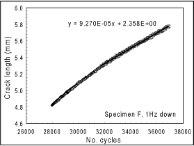
To determine the crack growth rate associated with each test block, a crack length vs. cycles plot was produced for each block of data (1mm crack increment). Typically, there was a transient in the growth rate following each frequency change, so this portion of the data was excluded from the analysis. It was generally found that the final 0.5mm of crack growth within each block exhibited a constant crack growth rate, so a linear fit was applied to this portion of the data, and a mean crack growth rate determined, as illustrated in Figure 3.
 |
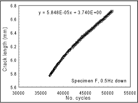 |
| Fig.3. Determination of crack growth rate from best fit line through second half of step of crack depth versus number of cycles |
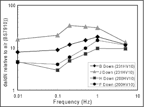
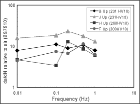
Test data from the first four (frequency scanning) tests are illustrated in Figure 4, compared with standard air data from BS 7910. Samples B and J corresponded to a higher hardness microstructure, while specimens F and H exhibited a lower hardness. Each test started at a frequency of 5Hz (right hand side of Figure), and the frequency was then shed (in 1mm increments) to 1, 0.5, 0.2, 0.1, and then 0.01Hz. The solid points in Figure 4 represent this portion of the test (frequency decreasing). The frequency was then increased again to 0.1, 0.2, 0.5 and then 1Hz. Figure 4b relates to this later portion of the test (frequency increasing).
 |
 |
a) Downward frequency steps.
The first part of the test was at 5Hz, down to 0.01Hz; |
b) Upward frequency steps from 0.01 up to 1Hz. |
| Fig.4. Dependence of crack growth rate on frequency. Specimens B and J are the harder microstructure, F and H the softer: |
The first point worth noting is that specimens B and J (hard) exhibited a consistently higher crack growth rate than specimens F and H (soft). Crack growth rates in the higher hardness microstructure appear to be a factor of 2-5 higher than in the lower hardness microstructure. However, the effect of frequency on crack growth rate is rather less clear. It was anticipated that crack growth rates at low frequency might be higher than those at higher frequency, due to the greater time available for environmental interaction. However, it would seem that under the conditions examined this was not the case. Indeed, for the lower hardness samples the crack growth rate at 0.1Hz seems to be consistently lower than at 1Hz.
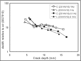
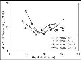
Test data from the second set of four tests, looking at the influence of crack depth, are illustrated in Figure 5. Here, specimens C and L have a higher hardness microstructure, and specimens E and K have a lower hardness microstructure. Frequency was alternately 1 and 0.1Hz, and the influence of crack depth determined by plotting each set of data on a separate graph. Figure 5a relates to the higher hardness microstructure and Figure 5b to the lower hardness microstructure.
 |
 |
| a) Specimens C and L (hard); |
b) Specimens E and K (soft) |
| Fig.5. Dependence of crack growth rate on crack depth: |
Post-test examination
Figure 6 shows an example of part of a corrosion fatigue crack. The crack is straight and shows no microstructural dependence. The harder microstructures were found to have mean hardnesses in the range 225-242HV10 and the softer ones 197-201HV10.
Fig.6. Part of fatigue fracture through specimen H (soft) showing no dependence of crack path on microstructure. Sample etched in 2% nital
Discussion
It is clear from Figures 4 and 5 that crack growth rates in the higher hardness microstructure are generally higher than those seen in the lower hardness microstructure. The magnitude of this effect varied somewhat and was a factor of 2-5 in the first series of tests, but only up to a factor of 2 in the second series of tests, which considered only two frequencies, ie 0.1 and 1.0Hz. However, there did seem to be a discernible difference in behaviour, so it is clear that even below the 250HV10 hardness limit there is still an effect of hardness on the material's fatigue performance in a sour environment.
In the higher hardness microstructure, sour crack growth rates were between 8 and 30 times higher than those seen in air. There is no obvious single effect of frequency, although the crack growth rate appears to be slightly higher between 0.2 and 1Hz (Figure 4). There is no indication that the crack growth rate at very low frequency (0.01Hz) is any higher than that seen at higher frequency for the chosen test conditions.
In the lower hardness microstructure there was again no indication that the crack growth rate at very low frequency (0.01Hz) was any higher than seen at higher frequency. Indeed, at 0.1Hz, the crack growth rate was consistently lower than that seen at 1Hz.
It is therefore clear that there does not appear to be a trend of increasing crack growth rate with decreasing frequency. Indeed, in some instances the crack growth rate appears to decrease with decreasing frequency (between 0.1 and 1Hz). This is most noticeable during the decreasing frequency (down) portion of the tests (Figure 4a) where the crack depth was in the range of 5-9mm. Examination of the data in Figure 5 suggests that crack growth rate may be sensitive to crack depth in this regime. The observed decrease in crack growth rate between 1 and 0.1Hz is therefore attributed to an indirect influence of crack depth, rather than an influence of frequency. Over the range examined, it is concluded that frequency does not have a significant effect on the observed crack growth rate. It is however noted that the observed frequency response may depend on the precise value of applied stress intensity range.
This lack of influence of frequency is in contrast to other published data where crack growth rates at very low frequency have been significantly higher (Figure 7). In the study by Eadie et al[5] crack growth rates were determined for X70 steel in a brine saturated with a test gas containing 10%CO2 and 1%H2S. At ΔK values of 332N/mm3/2 and 775N/mm3/2, a frequency effect was observed, which was more marked at the lower ΔK. At even lower ΔK (~240N/mm3/2) however, crack growth rates were similar to those in air. Since, at higher ΔK (330-770N/mm3/2) crack growth rate became limited by a frequency-dependent plateau, the maximum environmental effect (relative to air) was seen at intermediate ΔK.
The influence of frequency was also investigated by Buitrago et al.[6] where a frequency scanning technique was used to examine the corrosion fatigue behaviour of welded X80 steel in a sour brine based on NACE TM 0177 Solution B. All tests were carried out at ΔK=348N/mm3/2. The observed crack growth rate data suggest that while da/dN increases as the frequency is reduced, the crack growth rate appeared to be relatively insensitive to frequency between 0.1 and 1Hz.
It is worth noting that the absolute crack growth rate in the present work was somewhat lower than seen in either of these other programmes, and it is possible that the results were influenced by the slightly lower ΔK (300N/mm3/2) employed. Furthermore, the present work considered heat treated material representative of that likely within a HAZ, whereas the other two studies examined the behaviour of parent pipe. However, it is not clear why the frequency response seen in this work differs slightly from that seen in other studies.
Fig.7. Published data on the frequency dependence of crack growth rate in sour environments [5,6]
Although the explicit influence of crack depth was not being investigated in this work, it is interesting to note that there may be an influence of this variable on the observed crack growth rate. This is evident from the data described in Figure 5, and is perhaps more noticeable at low frequency (0.1Hz). Further data for crack depths in the range of 1-6mm would be very useful in determining the significance of this effect.
In particular, these data may help to explain a discrepancy between sour fatigue crack growth rate data, and sour endurance data. In some instances, the observed reduction in fatigue life (when strip specimens containing complete sections of girth weld are tested in a sour environment) is greater than the observed increase in crack growth rate (when fracture mechanics specimens taken from the same welds are tested in the same sour environment). The fact that fracture mechanics data are not able to reliably predict the overall fatigue performance of welds in a sour environment is clearly undesirable. A potential influence of crack depth on crack growth rate in the range of 1-6mm would certainly be significant when using fracture mechanics calculations to determine tolerable flaw sizes. As crack lengths are typically in this range (or shorter) for the majority of a structure's life, a better understanding of material behaviour in this regime is required to ensure that fatigue life calculations are conservative. A further discussion of this and related issues is presented in a parallel paper at this conference,[7] and in the light of the test data reported above, future phases of that programme are intended to include experimental studies of shallow crack fatigue behaviour in a sour environment.
The other factor potentially responsible for the discrepancy described above, is the fact that the early stages of fatigue crack growth are typically from a weld root toe, through HAZ microstructure that may be different to that sampled during fracture mechanics tests on actual welds. In particular, the work described above suggests that differences in microstructure or hardness, may result in differences in fatigue crack growth rate, irrespective of the crack depth. If the HAZ close to the weld root toe exhibits a higher hardness than that deeper into the weld, it may be reasonable to expect a greater environmental effect during endurance testing than during crack growth rate testing, as the early stages of crack growth will dominate overall behaviour. It is then conceivable that crack growth rate data appropriate to a given microstructure could be used to model the different stages of crack growth through a weld, and the observed differences could be reconciled.
Conclusions
Fatigue tests in a sour environment have shown that crack growth rate is dependent on microstructure. In particular, it has been demonstrated that for simulated HAZ microstructures, the crack growth rate in material exhibiting a 231HV10 hardness is higher than in material exhibiting a 200HV10 hardness.
For the specific combination of material, environment, stress ratio and ΔK examined in this work, it would appear that frequency has a relatively small effect on crack growth rate over the range examined (5 down to 0.01Hz).
There is some evidence to suggest that crack growth rates may depend on crack depth. This was most consistent in specimens exhibiting the harder (231HV10) microstructure.
Recommendations
When performing fracture mechanics calculations using fatigue crack growth rate data, it is important to ensure that the latter are associated with tests performed on material exhibiting a comparable microstructure to the component being modelled. In particular, for cracks propagating through HAZ material, differences in hardness may result in differences of crack growth rate, and this needs to be considered to ensure that fatigue life calculations are conservative.
For relatively shallow flaws it may be the case that crack growth rates in a sour environment are higher (for a given ΔK) than for longer flaws. It should therefore be recognised that in certain applications, defect assessments which use crack growth rate data derived from tests using deeply-cracked specimens may result in non-conservative life predictions. To avoid this possibility, test data should be derived from specimens containing cracks of a size comparable to those being assessed.
In cases where service loading includes a significant contribution from low frequency cycles, the potential influence of frequency on fatigue crack growth rate should be considered. Although the data determined in this work displays a relatively weak frequency dependence, other published data have shown that this variable can have a significant effect. At very low frequencies, rates of corrosion fatigue crack growth can be significantly higher than seen at higher frequencies, and experimental data for the particular material and environment of interest should be determined.
Acknowledgements
This work was carried out within the Core Research Programme of TWI which is funded by the Industrial Members of TWI.
References
- Woollin P and Tubby P J: 'Fatigue crack propagation in C-Mn steel HAZ microstructures tested in air and seawater', Paper 2601, Offshore Mechanics and Arctic Engineering Conference (OMAE 1998) Lisbon.
- NACE MR0175/ISO 15156 First Edition 2003: 'Petroleum and natural gas industries - Materials for use in H2S-containing environments in oil and gas.' NACE International, Houston, Texas, 2003.
- BS ISO 12108:2002: 'Metallic materials. Fatigue testing. Fatigue crack growth method.' BSI, London, 2002.
- NACE TM0177-2005: 'Laboratory testing of metals for resistance to sulphide stress cracking and stress corrosion cracking in H2S environments.' NACE International, Houston, Texas 2005.
- Eadie R L et al.: 'Corrosion fatigue and near-neutral pH stress corrosion cracking of pipeline steel in very dilute carbonate/bicarbonate with and without the presence of hydrogen sulphide using the compliance technique', Paper No. 03527, Proc. Corrosion 2003, NACE International, Houston, TX, 2003.
- Buitrago J et al.: 'Effect of loading frequency on fatigue performance of risers in sour environment', Paper 51641, Offshore Mechanics and Arctic Engineering Conference (OMAE 2004), Vol.III Materials Engineering, ASME, 2004.
- Holtam C and Baxter D 2007: 'Development of environment assisted cracking assessment methods - Material behaviour in the shallow crack regime.' Submitted to OMAE 2008.