Coatings for Offshore Applications by High Velocity Wire Flame Spraying
M D F Harvey, S Shrestha and A Sturgeon
Paper presented at NACE 2005 Houston, Texas, 3-7 April 2005.
Abstract
Most commercial high velocity oxy-fuel (HVOF) flame spraying systems are primarily designed for mechanised use in thermal spraying booths and are limited to powder-based consumables that are often much more expensive than wire materials. However, a smaller wire fed HVOF system has recently become available with simpler, portable control units. This system is of particular interest for depositing a wide range of wire-based consumables, e.g. aluminium, zinc and their alloys for sacrificial corrosion protection of offshore platforms, risers and piping, crude oil vessels and bridges. Other applications include corrosion resistant coating materials such as stainless steels and nickel alloys. The objective of this work were to compare the corrosion performance of the HVOF wire flame spray system with the twin wire arc-spray and HVOF powder processes for the preparation of coatings of pure aluminium, 316L stainless steel and nickel alloy 625. Coating characteristics such as porosity, oxide content and adhesion were evaluated. The corrosion properties of the coatings were compared using an accelerated potentiodynamic electrochemical corrosion test.
Introduction
Corrosion protection of steel structures by thermally sprayed aluminium and zinc has been used increasingly in the offshore sectors in recent decades. [1-3] The use of thermally sprayed aluminium for applications such as weather decks, oil tanks, ballast tanks, sanitary spaces, sewage holding tanks, fresh water tanks, fuel tanks and steam valves provides testimonial to the success of the technology. However, there is concern that coating durability is limited due to the coating quality that can be achieved using conventional wire flame and twin wire arc spraying processes. In particular, the quality of thermally sprayed coatings produced by these processes appears limited by porosity, oxide content and non-uniformity. Stringent requirements, particularly in deep seawater applications, necessitate the development of improved spraying systems that can deposit coatings of better quality for greater durability. The spraying of corrosion resistant alloys onto steel by high velocity oxy-fuel (HVOF) spraying has received much attention in recent years as a process for producing improved coatings for protection against corrosion and wear. The HVOF powder spraying process can deposit high quality coatings but is expensive and its use is generally restricted to small to medium sized components in the controlled environment of an enclosure with sound attenuation and particulate waste collection. Thus, there exists a need for a new process that can deposit coatings with improved properties and at lower costs that could be considered also for on-site deployment.
This report evaluates a new high velocity flame spray system that uses consumable in a wire form. A project was undertaken to compare coatings produced using the high velocity wire flame spray process with those deposited using conventional arc wire and HVOF powder spraying. Coatings were prepared of pure aluminium (min. 99.5% Al), 316L stainless steel and nickel alloy 625. These materials were selected for preliminary evaluation due to their extensive industrial applications. Coatings were deposited using consumable feed stocks in both wire and powder forms. Coatings were examined to determine microstructure (porosity, oxide content, homogeneity); bond strength and preliminary corrosion performance in a salt solution.
Experimental procedure
Coating preparation
Test pieces of 40x40x6mm were cut from 40x6mm hot rolled C-Mn steel strip, conforming to BS EN 10025:1993:S355J2G4. These were prepared to a 'White-Metal Blast-Cleaned Surface Finish' in accordance with NACE No. 1, by degreasing with petroleum ether and grit blasting at 80psi with grade 20 angular, fused-alumina grit (BS410, 1-1.2mm) immediately prior to coating. Three coating materials, pure aluminium (min. 99.5% Al), 316L stainless steel (UNS S31603) and nickel alloy 625 (UNS NO6625) all in wire and powder forms, were selected for investigation.
High velocity wire flame sprayed coatings (designated 'HV' hereafter) were prepared using the propylene-fuelled, HVT HVw 2000-wire system with 1.6mm diameter wire consumables (Figure 1a). The system has a wire push system driven by an electrical motor attached to the wire drive system. Twin wire arc-sprayed coatings (designated 'AS') were prepared using a Metallisation 528 arc-spray system (Figure 1b), with 1.6mm diameter wires drawn continuously from two separate spools using a gun wire pull system. The drive unit for this system includes a constant mesh gear system powered by an electronically controlled electric motor giving variable speed control. HVOF powder sprayed coatings (designated 'HVOF') were prepared using the kerosene-fuelled Praxair JP-5000 HVOF system (Figure 1c). This system has a radial powder injection system with powder injected downstream of the combustion nozzle. Injection to this lower pressure area promotes better powder mixing, more even heating, less oxidation and higher particle velocities. Manufacturers' recommended spraying parameters were used to prepare all the coatings evaluated in this study.
Fig.1a) High velocity wire flame spraying gun
Fig.1b) Twin wire arc spraying gun
Fig.1c) High velocity oxy-fuel (HVOF) powder spraying gun
Coating characterisation
Coated samples were cut and mounted in araldite in cross-section, then ground and polished to a 1µm diamond finish using standard metallographic preparation techniques for microscopic examination. Porosity was measured from a captured image obtained from the polished cross section using an In2ViewCat-Pro imager analyser. Coating oxygen content was measured from detached coating samples by an inert gas fusion technique using a Leco TC 136 analyser. Coating bond strength was measured by the tensile pull method in accordance with adhesion test procedure ASTM D4541, using a DFD Instruments GM0103 P.A.T. adhesion tester. Roughness of the as-sprayed coating surface was measured using aSurfcom 130A surface profilometer.
Electrochemical testing
Coated test specimens were cut to a size of 15x15mm. A stainless steel rod was welded to the rear face of the specimens and mounted in a non-conducting epoxy with the coating face exposed (Figure 2a). A strip of electromask paint was applied around the perimeter of the coating/epoxy interface, leaving only a 10x10mm area exposed to the corrosion test. Application of this non-conductive paint seals the coating/epoxy interface, thus preventing penetration of the electrolyte solution to the steel substrate from the edges of the coupon. The coated specimens were cleaned with alcohol and rinsed in de-ionised water prior to the electrochemical testing. The coatings were tested in the as-sprayed condition.
Electrochemical corrosion tests were conducted using a three-electrode cell arrangement attached to a computer-controlled potentiostat in accordance with ASTM G61-86 (Re-approved 1998), in an electrolyte of 3.5wt % NaCl solution made with deionised water at 20±2°C (Figure 2b). The solution was de-aerated continuously during the test with a nitrogen purge.
b) Three-electrode electrochemical cell (RE-reference electrode, WE-working electrode (coated sample), AE-auxiliary electrode)
Fig.2. Schematic diagrams
The coated surface i.e. the working electrode was exposed to electrolyte and the rest potential 'E corr' (or free corrosion potential) was allowed to stabilise for one hour prior to anodic polarisation. The coated surface potential was measured using a reference saturated calomel electrode (SCE). The coating area (10x10mm) exposed to the electrolyte was polarised anodically from its rest potential to a more positive potential at a rate of 10mV.min-1 . A plot of the current density was recorded as the polarisation potential was increased. The electrochemical study did not account for the surface area variations due to the surface roughness of the sprayed coatings.
Results
Microstructure characterisation
Aluminium Coatings. The twin wire arc-sprayed aluminium coating (AS-Al) is a porous coating typical of this process, featuring layers formed from impacted molten particles, with coating porosity varying from one region to another (Figure 3a). Porosity is located mainly between individual spray particles where there is insufficient deformation of the molten particles on impact. The HVOF powder (HVOF-Al) and HV wire flame sprayed (HV-Al) coatings are characterised by dense and homogeneous coating microstructures with very little coating porosity (Figures 3b, 3c). The HV-Al coating contains the lowest amount of porosity, followed by the HVOF-Al coating, both with porosity levels below 1% (Table 1). In contrast, the AS-Al coating has a significantly higher porosity level in excess of 6%.
Table 1 Coating characteristics
| | Porosity,
vol. % | Oxygen,
wt. % | Surface roughness,
µmRa | Coating adhesion,
MPa | Free corrosion
potential
E corr , mV (SCE) |
|---|
| AS-Al |
5.6 |
1.0 |
18 |
25 |
-747 |
| HVOF-Al |
0.8 |
0.2 |
11 |
14 |
-736 |
| HV-Al |
0.3 |
0.4 |
6 |
12 |
-1190 |
| |
|
|
|
|
|
| AS-316 |
3.0 |
5.8 |
11 |
26 |
-579 |
| HVOF-316 |
3.4 |
0.6 |
8 |
20 |
-486 |
| HV-316 |
0.3 |
8.2 |
6 |
25 |
-446 |
| |
|
|
|
|
|
| AS-625 |
0.5 |
3.7 |
13 |
36 |
-580 |
| HVOF-625 |
0.3 |
0.9 |
5 |
87 |
-225 |
| HV-625 |
0.3 |
6.3 |
6 |
29 |
-98 |
The HVOF-Al coating has the lowest oxygen content, followed by the HV-Al coating, both below about <0.5wt% (Table 1). The AS-Al coating has a slightly higher level of oxygen content of about 1%. It is assumed that the oxygen content is associated with the presence of aluminium oxide. These values correspond to oxide levels of less than 1wt% for the HV-Al and HVOF-Al coatings and about 2wt% for the AS-Al coating. The twin wire arc-sprayed aluminium (AS-Al) coatings have a rough as-deposited surface with a typical roughness of about 18µmRa and non-uniform coating thickness. The HVOF-Al coating has a smoother as-sprayed surface finish (11µmRa) with a more uniform coating thickness over the entire coated specimen. The HV-Al coating surface has the smoothest surface finish(6µmRa) and the most consistent coating thickness.
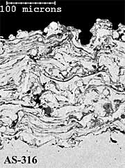
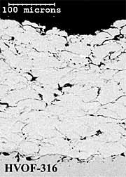
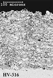
316L Stainless Steel Coatings. The twin wire arc-sprayed 316L stainless steel coating (AS-316) has a layered particulate structure (Figure 4a). The coating also contains some porosity, which is mainly located between individual particle splats. The HVOF powder (HVOF-316) coating comprises well-defined, deformed spray particles with some inter-particulate porosity (Figure 4b). The HV-316 coating cross-section shows a dense, layered microstructure (Figure 4c), with less coating porosity than the AS-316 and HVOF-316 coatings (Table 1). The higher levels of coating porosity manifest mainly as inter-particulate voids in AS-316 and inter-lamellae voids in HVOF-316. The HVOF-316 coating contains the lowest amount of oxygen at 0.6%. The AS-316 andHV-316 coatings have much higher levels of oxygen at 6 % and 8% respectively. Once again, the HVOF-316 and HV-316 coatings have a smoother as-sprayed surface finish (8µmRa) than the AS-316 coating (11µmRa).
|
|
 |
|
Fig.4. Back-scattered electron images of polished cross-sections of as-sprayed AS-316; HVOF-316 and HV-316 coatings
|
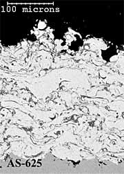
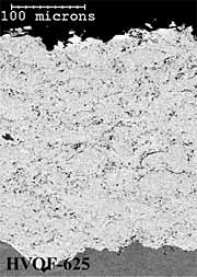
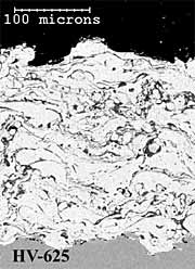
Alloy 625 Coatings. The twin wire arc-sprayed alloy 625 coating (AS-625) has a dense and layered particulate microstructure (Figure 5a). The HVOF powder coating (HVOF-625) has a dense coating microstructure with very fine scale porosity (Figure 5b). The HV wire flame sprayed (HV-625) coating has a layered, particulate microstructure (Figure 5c). The AS-625 coating has a slightly higher level of coating porosity (~0.5%) than either the HVOF-625 or HV-625 coatings (~0.3%) but all coating porosity levels were quite low (Table 1). In common with the 316L stainless steel coatings, the HVOF powder coating (HVOF-625) has the lowest (~0.9wt%) and the HV wire flame sprayed (HV-625) has the highest (~6.3wt%) oxygen content (Table 1). In common with the aluminium and 316L stainless steel coatings, the HVOF-625 and HV-625 coatings have smoother as-deposited surface finishes (6µmRa) than the AS-625 coating (13µmRa).
 |
 |
 |
|
Fig.5. Back-scattered electron images of polished cross-sections of as-sprayed AS-625; HVOF-625 and HV-625 coatings
|
Coating bond strength
Aluminium. The AS-Al coatings have the highest bond strength at about 25MPa (Table 1). The bond strength values of HVOF-Al and HV-Al coatings are similar at 14 and 12MPa respectively. The HV-Al and HVOF-Al coatings fail mainly at the coating to substrate interface, whereas the AS-Al coating displays primarily cohesive failure within the coating.
316L stainless steel. The AS-316 coatings have the highest bond strength at about 26MPa, followed by the HV-316 coatings with a similar bond strength of 25MPa. The HVOF-316 coating has the lowest bond strength of about20MPa. All the 316L stainless steel coatings fail mainly at the coating to substrate interface.
Alloy 625. The HVOF-625 coating has the highest bond strength at about 87MPa. The AS-625 and HV-625 have bond strength values of about 36 and 29MPa respectively. The mode of failure in the HVOF-625 coating is primarily within the adhesive, suggesting that the actual coating bond strength exceeds the measured value of 87MPa. The mode of failure in the AS-625 coatings is mainly cohesive failure within the coating, whereas the HV-625 coating fails mainly at the coating to substrate interface.
Electrochemical Polarisation
Aluminium. The rest potentials (E corr) of AS-Al and HVOF-Al are -747 and -736mVsce respectively, compared to -1190mVsce for the HV-Al coating ( Figure 6). The AS-Al and HVOF-Al coatings are characterised by similar electrochemical response including high initial current densities. Although both coatings display a slight reduction from the measured initial high anodic current density immediately upon polarisation, a rapid further increase of the current density is observed when the polarisation potential is raised above -750mVsce.
Fig.6. Anodic polarisation plots (forward scans) of aluminium coatings in as-sprayed condition, in de-aerated static 3.5% NaCl solution at 20°C
In contrast, the HV-Al coating displays a more passive behaviour at potentials below about -750mVsce. There is a stable current density region of about 10µA.cm -2 between -1100 and -750mV SCE. The passive range, i.e. Eb-E corr of about 480mV, is representative of the HV-Al coating and is characterised by good resistance to the initiation of corrosion attack under the test conditions.
Fig.7. Anodic polarisation plots (forward scans) of stainless steel 316L coatings in as-sprayed condition, in de-aerated static 3.5% NaCl solution at 20°C
Fig.8. Anodic polarisation plots (forward scans) of nickel alloy 625 coatings in as-sprayed condition, in de-aerated static 3.5% NaCl solution at 20°C
316L Stainless Steel. The HVOF-316 and HV-316 coatings are characterised by more positive rest potentials 'E corr' than the AS-316 coating. Rest potentials are -486, -446 and -579mVsce respectively. Although the polarisation plots do not show electrochemical behaviours that can be regarded as passive, a moderate increase of the current density upon anodic polarisation for the HVOF-316 coating is indicative of corrosion activities occurring at the surface at a slower rate. The HV-316 coating does not display a low current density region. TheAS-316 coating is characterised by a highly active coating surface shown by an immediate rapid rise in current density upon anodic polarisation.
Alloy 625. The AS-625 and HVOF-625 coatings are characterised by much more negative rest potentials of -580 and -225mVsce respectively than the HV-625 coating, which has a rest potential of -98mVsce. The HVOF-625coating is characterised by a very low current density (<5µA.cm-2) over a wide potential range (-200 to +300mVsce) upon anodic polarisation and can be considered as exhibiting a passive behaviour over this potential range. The HV-625 coating displays a smaller potential range of about 100mVsce from its E corr , where the current density is low (<5µA.cm-2) and indicates that this coating can offer some protective capability, which is nevertheless inferior to the HVOF-625 coating. The AS-625 coating is characterised by a highly active coating surface indicated by an immediate rise in the current density upon anodic polarisation.
Discussion
The anodic polarisation plot of the HV-Al coating is quite different to those seen for the HVOF-Al and AS-Al coatings. The much lower rest potential and a passive behaviour below -750mVsce suggests that that this aluminium coating is less active when first immersed in an aqueous NaCl solution, indicating good resistance to corrosion initiation. It is often considered necessary to allow thermally sprayed aluminium coatings to stabilise over a longer exposure period, typically a minimum of two weeks to get a measure of the stable rest potential values. As such the rest potential recorded after a one-hour stabilisation period in the current laboratory tests may not reflect the true rest potential values that the sprayed coatings display over the longer period. However, this is an interesting observation and the free corrosion potential of about -1190mV displayed by the HV-Al coating indicates its capability to provide immediate cathodic protection to the carbon steel substrate upon immersion. The more positive potential seen for the AS-Al coating may be due to the higher level of porosity in this coating with the underlying steel substrate contributing to the initial rest potential. However, it is difficult to explain the result for the HVOF-Al coating, but it suggests that even though the measured porosity was relatively low, the test solution is penetrating the coating to the underlying steel substrate, causing the rest potential to become more positive.
The anodic polarisation plots of the stainless steel coatings show the HVOF-316 coatings appear to have slightly better corrosion resistance compared to the HV-316 coating. This is probably due to the occurrence of less oxidation during the HVOF spraying of this alloy. It is believed that oxidation primarily forms chromium-containing oxides leading to a significant depletion of chromium from the coating alloy. However, none of the 316 stainless coatings display significant passivity in the test solution and the inferior corrosion resistance of the HVOF-sprayed 316 coating compared to a wrought alloy has been reported elsewhere. [4]
The anodic polarisation plots suggest that the HVOF-625 coating has the highest corrosion resistance and can be considered as a passive protective layer. Such behaviour can only be expected from a coating having very low porosity and oxide levels. The corrosion behaviour of the HVOF-625 coating is in good agreement with other publications. [5-6] The HV-625 coating displays less corrosion resistance; and the AS-625 coating has an active surface with low resistance to corrosion attack. These results are again probably explained by the presence of higher levels of oxide and depletion of chromium and nickel from the alloy 625 coating.
Conclusions
The main conclusions of this study are:
- The HV wire flame spraying process produces a uniform aluminium coating with low levels of oxidation (<0.5%) and porosity (<0.5%).
- Short-term electrochemical tests suggest that the HV wire flame sprayed aluminium surface is passive and will attain a potential level below -1100mVsce shortly after immersion in a de-aerated 3.5wt % NaCl solution. This potential value is sufficiently negative to polarise and offer cathodic protection to any exposed steel shortly after immersion.
- The twin wire arc and HVOF sprayed aluminium coatings are active on immersion in a de-aerated 3.5wt % NaCl solution with potential levels insufficient for cathodic protection of steel during this initial period. This behaviour would not be expected over longer immersion durations.
- The HV wire flame spraying process produces low porosity (<0.5%) coatings of 316 stainless steel and nickel alloy 625, however the oxide level in the coatings (>5wt%) is much higher than that achieved in HVOF coatings and is similar to those seen in twin wire arc sprayed coatings.
- HVOF sprayed coatings of 316 stainless steel and nickel alloy 625 display superior corrosion performance in the laboratory test condition compared to the twin wire arc or HV wire flame sprayed coatings.
- The new HV wire flame spray process can be considered an alternative to conventional twin wire arc spraying process for the preparation of aluminium coatings where improved quality coatings are required. The HVOF process still is the most appropriate process for the deposition of coatings of 316 stainless steel and nickel alloy 625.
Acknowledgement
This paper has been produced from a TWI Core Reseach Programme report funded by the Industrial Member Companies of TWI.
References
- Rosbrook T, Thomason W H and Byrd J D: 'Flame sprayed aluminium coatings used on subsea components'. Material Performance, September 1989, pp.34-38.
- Fitzsimons B: 'Thermal spray metal coatings for corrosion protection'. Institute of Materials, No.2, 1994, pp.27-46.
- Fischer K P, Thomason W H, Rosbrook T and Murali J: 'Performance history of thermal-sprayed aluminium coatings in offshore service'. Material Performance, April 1995, pp.27-35.
- Sturgeon A: 'Improved corrosion resistant coatings prepared using a modified diamond Jet HVOF spraying system', Proceedings of the International Thermal Spray Conference (ITSC 2002), 4-6 March 2002, Publ: DVS-Verlag, Dusseldorf, ISBN3-87155-783-8, 2002, 506-509.
- Sturgeon A: 'The corrosion behaviour of HVOF sprayed stainless steel and nickel alloy coatings in artificial seawater', CORROSION 2003, San Diego, 16-20 March 2003, Paper 03245, Publ: NACE, Houston, 2003.
- Shrestha S and Sturgeon A J: 'Use of advanced thermal spray processes for corrosion protection in marine environments', Surface Engineering Vol.20 No.4, 2004.