TWI Ltd
E-mail: suman.shrestha@twi.co.uk
Paper published in EUROCORR 2005 Lisbon, Portugal, 4-8 September 2005
Abstract
Thermal sprayed aluminium (TSA) coatings are widely specified for the protection of steels from aqueous corrosion, including offshore structures and components that are exposed to seawater immersion, tidal and splash zone environments. In this paper, the performance of TSA coatings prepared by conventional and newer wire thermal spray systems is presented. The TSA coatings were characterised in terms of deposition efficiency, coating microstructure including porosity and oxide content, surface roughness and coating adhesion. A cost analysis for coating deposition using the various systems is included.
The corrosion behaviour of the coatings was compared using an accelerated electrochemical corrosion test method. In addition, longer-term free immersion tests of up to 31 days were conducted in 3.5wt% NaCl solution, pH 7.9-8.2,22-25°C. The TSA coating performance was quantified in terms of its free corrosion potential and the corrosion rate which was estimated from linear polarisation resistance (LPR) measurements. The ability of the TSA coatings to provide adequate cathodic protection to exposed bare steel in immersed saline environment has been demonstrated. The newer systems have been shown to produce TSA coatings of improved quality and the effect of this on longer-term corrosion protection of steel substrates in immersed saline environment is discussed.
1. Introduction
Thermal sprayed aluminium (TSA) coatings are widely specified for the protection of steels from aqueous corrosion in seawater environment e.g. offshore structures, risers, pipe components and ship structures. [1,2] The main service conditions for the application of TSA include seawater immersion, tidal and splash zone and marine atmosphere. [3] The successful use of TSA coatings in offshore applications such as tension leg elements and production risers in deep seawater have been reported in the literature. [4,5]
Toughness, low maintenance requirements, and long-term service life are among the desirable properties offered by TSA coatings for offshore applications. [1,6] The basic properties of a TSA coating for long-term service are its barrier characteristics combined with good adhesion and an ability to provide cathodic protection to exposed steel. It was reported that a 200µm thickness TSA coating would provide a service life in excess of 30 years in a splash zone environment if optimised. [7] Key factors for optimisation include TSA alloy composition; surface preparation; choice and application of a sealer; service application; electrochemical/galvanic exposure conditions; coating application techniques and process parameters. The stringent requirement of the offshore industries (e.g. oil and gas) to have a maintenance free coating system, with an expectation of up to 50 years life in severe environments, has increased interest in TSA coatings asa viable economic alternative to paint based systems. [8] Although it has been demonstrated that TSA deposited by conventional spray systems can work well over extended periods, incidents of premature coating failure due to blistering and detachment have been recorded, indicating that coating quality and coating application procedure is extremely important. [4] Porosity, oxide content and non-uniformity in the TSA coatings produced by the conventional systems are believed to result in reduced corrosion protection and shorter lifetime. Recent developments in spraying equipment via modification in nozzle and gun design, and process parameters (such as higher gas flow rates and gas pressures) are believed to produce TSA coatings with improved properties. In this paper, the microstructure, physical properties, deposition cost and electrochemical corrosion characteristics of TSA coatings applied onto C-Mn steel, using conventional and newer wire thermal spray systems have been assessed.
2. Experimental procedures
Coating preparation
TSA coatings were deposited to a nominal thickness of 250-300µm onto C-Mn steel (BS EN 10025:1993:S355J2G4) substrates using min.99.5%Al wires. Four commercial spraying systems were used: a) MK73 wire flame spray system(referred to as 'FS') is a conventional wire flame spray system that used propane as the fuel gas; b) 528 electric arc spray system (referred to as 'AS') - a conventional twin wire electric arc spray system that used compressed air asthe propellant; c) Pure coat inert gas shroud arc spray system (referred to as 'PC') system with nitrogen as the propellant and the shielding gas. This system differs from conventional arc spray systems that use air as the propellant and have no shielding gas. All three spraying systems described above are manufactured by Metallisation Ltd, UK.
Table 1 Summary of test specimens and spraying parameters
| Identification | Spraying system | Wire diameter | No of wires | Current | Voltage | Compressed gas pressure | Propane pressure | Oxygen pressure |
|---|
| mm | | A | V | psi | psi | psi |
|---|
| FS |
MK73 |
2.3 |
1 |
- |
- |
Air at 65 |
25 |
39 |
| AS |
528 |
2.3 |
2 |
200 |
30 |
Air at 73 |
- |
- |
| PC |
Purecoat |
1.6 |
2 |
200 |
34 |
Nitrogen at 78.4 |
- |
- |
| HV |
HVw 2000 |
1.6 |
1 |
- |
- |
Air at 100 |
60 |
80 |
The HVw 2000 high velocity wire flame spray system (referred to as 'HV') manufactured by HVT LLC, USA is typical of a new range of lightweight and portable wire flame spray systems becoming available commercially. This system uses propane as the fuel gas, oxygen and compressed air, all at higher pressures than conventional flame spray systems. As a result of this, higher gas and particle velocities are achieved. Some details and process parameters for each spray system is given in Table 1. Immediately prior to coating deposition, steel substrates were prepared to 'White Metal Finish' to NACE No.1 or Sa3. This was achieved by degreasing with petroleum ether and grit blasting at 80psi using grade 20angular fused alumina grit (BS410, 1.0-1.2mm,) followed by an air blast and further degreasing with petroleum ether solution. The TSA coating was applied at a laboratory temperature of 18-20°C, 45% relative humidity and without preheating the substrate. Coatings were prepared by placing the steel substrates on a rotating turntable while the spray gun mounted on a robot arm, was scanned across the surface of the test pieces in a series of vertical passes untila 250µm coating thickness was obtained.
Coating characterisation
A cross section of each coating was prepared using standard metallographic techniques and was examined using a scanning electron microscope (SEM). The level of porosity was measured from the cross sectional images using image analysis software. The oxygen content was measured in samples of coating detached from the substrate, using the inert gas fusion technique with Leco TC 136 equipment. Estimates of oxide levels in the coatings were calculated on the assumption that the detected oxygen was associated with the presence of Al2O3. Roughness (R a) of the as deposited coating surface was measured using a Surfcom surface profilometer. Coating hardness was measured using a Leitz Wetzlar miniload hardness tester on polished cross sections with a load of100g. Coating adhesion was measured in accordance with ASTM D4541-95, using a portable adhesion tester manufactured by DFD Instruments.
Process economics
The relative cost of coating deposition using each process was estimated, taking into consideration the energy, consumables required and assumed labour costs. Each process was evaluated and compared in terms of coating application rate and cost to deposit 1m2 of coating to a thickness of 250µm.
Electrochemical polarisation
The electrochemical corrosion behaviour of the coated test pieces was evaluated using the anodic polarisation test method similar to that described in ASTM G-61. The coating surface was tested in the as-sprayed condition. The corrosion test method comprised anodic polarisation in nitrogen purged 3.5wt% NaCl solution at 22-25°C, pH 7.9-8.2. A square coated specimen was encapsulated in a non-conductive epoxy resin with 1cm2 coating surface immersed in the test solution. After a stabilisation period of one hour, the free corrosion potential 'E Corr ' of the test surface was recorded relative to a reference saturated calomel electrode (sce). The coated specimen was then anodically polarised from its E Corr at a rate of 10mV.min-1 , whilst the resulting current density was measured using a platinum auxiliary electrode. A plot of anodic current density in µA.cm-2 was obtained as a function of the applied potential (mV sce). Polarisation curves were also obtained for wrought C-Mn steel (type 50D) and wrought aluminium (min.99.5% Al) specimens. The surface of the wrought specimens was abraded on a 600-grit SiC paper and then degreased with alcohol prior to testing.
Long-term E Corr and LPR measurements
Coated disc specimens (Ø38x6mm) with an electric rod welded to the rear face (uncoated side) of the specimen were encapsulated in a non-conductive uPVC specimen holder. Instant Aradite ® was applied around the perimeter of the coating/specimen holder interface, giving a Ø36mm surface area for the corrosion testing. Duplicate test specimens for each coating type with a Ø8mm defect,referred to as a holiday (~5% by area of the substrate) were exposed to 40 litres of 3.5wt% NaCl solution. For comparison, coated specimens without a defect (coating holiday) were also tested. The steel specimen was tested in a separate tank to avoid contamination of rust from the steel specimen. The electrolyte solution was re-circulated using a submersible pump at 0.3 l.min-1 and was continuously aerated using compressed air. The oxygen level was measured at 7.3-9.5ppm during the 31day-exposure. The solution temperature was maintained at 22-25°C and the pH at 7.9-8.2.
E Corr was monitored every hour for 31 days. The linear polarisation resistance (LPR) was recorded every hour over the 31-day period by polarising ±10mV from its E Corr at a scan rate of 10mV.min-1 . The equipment used was a computer-controlled 16-channel potentiostat (GILL16) from ACM Instruments. The calculation of the corrosion rate (CR) using the LPR technique is achieved by determining a corrosion current density 'i corr ', developed by Stern and Geary, which is calculated using the following mathematical equation:
mV (2)
where, ΔE/Δi = R p , slope of the polarisation resistance, ohm.cm2 ; b a and b c = anodic and cathodic Tafel constants in mV.decade-1 . The B values used for aluminium and steel in seawater were 18 and 25mV respectively and were taken from the NACE literature [9] . The corrosion current density was related directly to the corrosion rate using the following equation:
mm/y (3)
EW = equivalent wt. of the corroding species (g); ρ = density of the corroding species (g.cm-3)
In these calculations, the corroding species were taken to be aluminium (Al3+) for the coated specimens and iron (Fe2+) for the uncoated steel. Upon completion of the long-term immersion test, the specimens were rinsed in distilled water and oven dried for 24 hours at 40°C, followed by visual examination and photography of the specimen surface. The objective of this work was to characterise and compare the TSA coatings produced by various wire thermal spray processes in similar test conditions.
3. Results
Coating microstructures
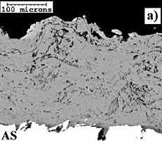
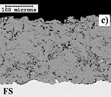
Back-scattered SEM images of the coatings are shown in Fig.1. The images of the cross sections clearly show layered structures of the impacted molten particles or lamella, with different amounts of coating porosity and oxide stringers typical for thermal sprayed coatings. Coating porosity is mainly interlamellar and at areas where there is insufficient deformation upon impact of the molten particles. The high velocity (HV) wire, flame sprayed (FS) and Purecoat (PC) sprayed coatings show a smooth and uniformas-sprayed surface. The high velocity (HV) coating shows the least variation in coating thickness, ranging between 222-242µm, while the flame sprayed (FS) and Purecoat (PC) coatings have a slightly wider thickness range between202-261µm and 219-280µm respectively. The arc sprayed (AS) coating shows variation in coating thickness, ranging between 224-303µm. Various characteristics of the coatings investigated are presented in Table 2. The HV wire sprayed coating displayed the lowest amount of porosity at about 2.4%, followed by the flame sprayed (FS) coating with 4.7% and the Purecoat (PC) with up to 5.5% porosity. The arc sprayed (AS) coating had about 6.3% porosity. Oxygen contents measured from the coating samples show that there are some differences between the prepared coatings. It is apparent that the flame sprayed (FS) coating displayed the lowest amount of oxide at 0.5%.The high velocity (HV) wire flame and Purecoat (PC) sprayed coatings displayed similar values of about 1% of oxide level. The arc sprayed (AS) coating had an oxide level in excess of 2%. Data in Table 2 show that the high velocity (HV) wire sprayed coating has a very smooth surface finish with about 5.5µm R a value, while the flame sprayed (FS) and Purecoat (PC) coatings had R a values of about 10.5 and 12.6µm respectively. Surface roughness values displayed by the arc sprayed (AS) coatings were higher at about 15.4µm R a . Measured Vickers hardness values were higher (above 50HV0.1) for the coatings prepared with the newer systems.
| a) arc sprayed |
b) Purecoat inert gas shroud sprayed |
 |
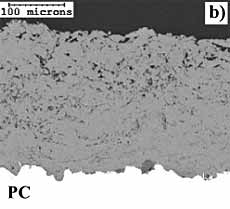 |
| c) flame sprayed, and |
d) HV wire flame sprayed aluminium coatings |
 |
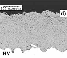 |
| Fig.1. Back-scattered electron image of a cross section of: |
Table 2 Some comparisons between the various spraying systems
| Coating type | Deposition efficiency (DE) | Deposit rate (DR) | Coating cost* | Coating characteristics and properties | Free corrosion potential (Ecorr) |
|---|
| Porosity | Oxide | Surface roughness | Vickers hardness | Coating adhesion |
|---|
| % | kg.h-1 | £.m-2 | Vol.% | wt.% | Ra, µm | HV 0.1 | MPa | mV sce |
|---|
| FS |
64 |
0.8 |
32.43 |
4.7 |
0.5 |
10.5 |
41.3 |
7 |
-1076 |
| AS |
43 |
2.5 |
13.52 |
6.3 |
2.1 |
15.4 |
43.7 |
20 |
-900 |
| PC |
75 |
4.6 |
16.15 |
5.4 |
1.0 |
12.6 |
50.7 |
19 |
-1035 |
| HV |
70 |
1.4 |
24.21 |
2.4 |
1.0 |
5.5 |
54.7 |
11 |
-1050 |
| * Includes labour at £30.h-1 |
Coating adhesion
The flame sprayed (FS) coating displayed the lowest adhesion value of about 7MPa (Table 2), while that for the high velocity (HV) wire flame sprayed coating was about 11MPa. The arc sprayed (AS) coating displayed the highest bond strength followed by the Purecoat (PC) sprayed coatings with adhesion values of 20 and 19MPa respectively. Examination for the mode of failure suggested that the flame sprayed (FS) and high velocity (HV) wire sprayed coatings failed mainly at the coating to substrate interface (coating adhesion) whereas the arc sprayed (AS) and the Purecoat sprayed (PC) coatings displayed failure primarily within the coating layers (coating cohesion).
Deposit rate and deposition efficiency
The arc spray processes (AS and PC) had higher spray rates at about 2.5 - 4.6 kg.h -1 compared to about 1 - 1.5 kg.h -1 for the flame spray processes (FS and HV). The PC system showed the highest deposition efficiency (DE) of about 75% followed by the high velocity (HV) wire and conventional flame spray (FS) systems with DEvalues of 70% and 64% respectively. DE for the conventional arc spray (AS) system was about 43%.
Process economics
The cost to deposit a 250µm thickness of TSA coating using each process onto 1m2 surface area is shown in Table 2. The cost was estimated taking into consideration the consumable, labour and power (electric or oxy-fuel combustion) costs. These values were calculated using deposit rate and deposition efficiency measured in this work. Table 2 shows that the cost of coating production using the conventional wire flame spray system (FS) is about 25% higher than the high velocity (HV) wire system. Coating deposition costs using the electric arc spray systems(AS and PC) are lower than the gas flame spray counterparts (FS and HV) by about 50%.
Electrochemical polarisation
Anodic polarisation plots from the tests performed at 20°C are shown in Fig.2. It is noticeable that the uncoated steel (50D) is corroding very rapidly. This is shown by the immediate rapid increase of anodic the current density upon a small increase of potential from 'E Corr .' Figure 2 shows that all the coatings, including the wrought aluminium displayed a passive potential range shown by low current densities at potentials positive to E Corr , up to a breakdown potential of about -750mV sce . However, some differences in passive current densities can be seen between the coatings. Figure 2 shows the HV coating had the lowest passive current density and was similar to that for the wrought aluminium. The HV, FS and PC sprayed coatings as well as the wrought aluminium showed E Corr in the range of -1000mV sce . The AS coating displayed a less negative electrode potential 'E Corr ' at about -900mV sce .
Long-term E Corr , LPR and corrosion rate measurements
The free corrosion potentials of the coatings with a 5% holiday reach stable values by approximate 15 days, Fig.3. The arc sprayed coating with a 5% holiday (AS5%) and the Purecoat coating with a 5% holiday (PC5%) both displayed similar stable potentials of about -1080mV sce . The high velocity flame spray coating with a 5% holiday (HV5%) recorded a slightly less negative potential of about -1030mV sce . However, after 27 days of exposure all the coatings with a 5% holiday reached similar stable potentials of about -1080mV sce . This potential range of -1030 to -1080mV sce for the specimens with a holiday in the coating is sufficient to provide a good level of cathodic protection to the steel substrate. The stable free corrosion potential of the uncoated steel submerged in a similar solution was about -630mV sce . A cathodic protection potential requirement of -800 to -1050mV Ag/AgCl for submerged steel is well documented in various literatures. [9] Corrosion rates of the specimens with a 5% coating holiday and of the uncoated 50D specimen, calculated using the LPR technique are shown in Fig.4. These corrosion rates were calculated using the literature values of 'B' given in the experimental section.
Calculated corrosion rates for the various coatings (without and with a 5% holiday) and for the uncoated 50D steel specimen are given in Fig.5. The uncoated 50D steel specimen displayed a very high corrosion rate of about 433µm/y after 21 days of immersion, as expected. For the coatings with a 5% holiday present, corrosion rates were obtained in the range of 10 to 20µm/y. For the PC and HV coatings without a holiday, corrosion rates were low in the range of 4-5µm/y, whereas for the AS coating without a holiday, the corrosion rate was high and was about 14µm/y. The data inFig.5 show lower corrosion rates for the coatings produced using the high velocity (HV) and the Purecoat (PC) systems than for the coating produced using the arc spray (AS) system, in both conditions i.e. without and with a 5%holiday. These corrosion rates are estimates for the test duration of 31 days investigated in this work and provide a good comparison between the coatings produced by conventional and newer thermal spray systems in a 3.5wt% NaCl solution.
The very high corrosion rate of the uncoated 50D steel specimen on completion of the corrosion test was clearly discernible with a loss of substantial steel thickness (not shown in this paper). The surface of the coated specimens with a 5% holiday (AS5%, PC5% and HV5%) after the immersion test are shown in Fig.6. Closer examination of the holiday area from the coated specimens did not show any sign of corrosion on the exposed steel surface. The exposed holiday surface was fully protected and appeared unaffected due to immersion in the test solution, except that the machined surface had lost its glossy appearance due to a thin film build-up on the exposed steel surface. The coating surface exposed to the salt solution displayed a dark film build-up and some white corrosion product. The white corrosion product is believed to be the hydrated aluminium oxide 'bayerite'. Figure 6 also shows the least white corrosion product on the HV 5% coating surface.
4. Discussion
Coating deposition efficiency and application cost
The HV wire flame spraying system demonstrated an improvement in both deposition efficiency and coating deposition cost (70%, £24/m2) compared to a conventional flame spray system (64%, £32/m2). Conventional arc spraying, is most widely used in industry due to its very high productivity (high spray rate) and low coating deposition cost (£14/m2). The Purecoat system can give better coating quality yet still achieve a similar coating deposition cost (£16/m2) compared to the conventional arc spraying system. This competitive cost was due to its high spray rate. The coating deposition costs given above include a labour charge at £30/h. The higher deposition cost of the HV wire flame spray system compared to the arc spraying systems is mostly due to a longer deposition time leading to a greater labour cost.
Coating characteristics
The HV wire flame and the Purecoat arc spray systems are capable of producing TSA coatings with improved quality, that is lower porosity, lower oxide content, smoother surface finish and higher coating adhesion. The coatings produced by the Purecoat arc spraying system had an adhesion of about 20MPa, while for those produced by the HV wire flame spray system adhesion was in excess of 11MPa. These adhesion values are well above the acceptance limits for TSA coatings as defined by various industry standards, for example the NORSOK, BS 2569, and SSPC-CS 23. The improved characteristics of the coatings prepared using newer systems are believed due to improvement in the system design and in particular, for the HV wire flame system due to higher gas velocities and subsequent higher particle velocities.
Electrochemical corrosion behaviour
The results of the electrochemical polarisation tests conducted in a nitrogen-purged 3.5wt% NaCl solution at 20°C, suggest that there are some differences between the coatings produced by various systems. In particular, the conventional arc sprayed coating was shown to have an E Corr of about -900mV sce , which is about 100mV less negative than the potentials shown by the coatings sprayed using the newer systems. This less negative potential is believed due to the higher amount of oxide and porosity in the arc sprayed coating, giving a mixed potential of the coating and steel system upon immediate exposure to the test solution. The HV wire flame sprayed and the Purecoat arc sprayed coatings displayed a large passive region, where the current density was low, during the anodic polarisation scan. This large passive region was similar to that seen with the wrought aluminium and suggests that the coating on its own could act as a highly protective barrier. The conventional arc sprayed coating did not display such a passive region.
Free corrosion potential and corrosion rate
Free corrosion potential
The steady free corrosion potential 'E Corr ' values of the unsealed coating with a 5% holiday produced by the conventional arc, shrouded-arc and high velocity flame spraying systems after 10 days were about -1030 to -1080mV sce . This mixed potential range for the TSA/steel system indicated that the exposed steel was sufficiently polarised and protected. The potential range is similar to the NACE and NORSOK recommended cathodic protection potential range of -800 to -1050mV Ag/AgCl . The good level of cathodic protection to the exposed steel was confirmed by examining the test samples after 31 days, which showed no corrosion attack of the exposed steel surface at the holiday region.
Corrosion rate
Corrosion rates calculated from the LPR values were used to determine the rate at which the aluminium coating was lost when immersed in a 3.5wt% NaCl solution at a temperature of 22-25°C. The calculated corrosion rates were assumed to be due to dissolution of the aluminium coating only and were not contributed to by the underlying steel or due to the exposed steel substrate. The corrosion rates of TSA coatings produced with these newer systems with a 5%holiday were about 11-12µm/y. The corrosion rate of the conventional arc sprayed coating with a 5% holiday was about 20µm/y, which is about two times higher than the coatings produced by the newer systems having a similarsized holiday. The corrosion rates for the specimens without a holiday were substantially lower than for the specimens with a 5% holiday. This suggests that a 5% holiday will increase the rate at which the aluminium coating is lost. Reports in the literature indicate that longer-term protection can be expected in seawater based on field trials and actual service experience. In seawater, the corrosion rate will be lower due to the formation of a calcareous deposit on the exposed steel (cathode) and corrosion product films on the TSA (anode) surface and hence a longer coating life.
5. Conclusions
- Newer spraying processes such as the inert gas shrouded arc spraying (Purecoat) and high velocity wire flame spraying (HV w 2000) produced TSA coatings with low oxide levels at <1wt%, low porosity levels at <5% and smoother as-sprayed surface roughness. Adhesion in excess of 10MPa was achieved for the high velocity wire flame sprayed coating and about 20MPa for the shrouded arc sprayed coating, when applied onto a steel substrate without preheating. The coating preparation cost using the arc spray systems was considerably cheaper than that using the flame spray systems.
- TSA coatings prepared using the newer thermal spray processes had lower corrosion rates in an aerated 3.5wt% NaCl solution at temperatures of 22-25°C than the TSA coating produced using the conventional arc spray system. The coatings prepared using the newer processes and with a 5% coating damage had a corrosion rate of 11-12µm/y compared to 19µm/y when prepared using a conventional arc spray process. When undamaged (i.e. without a holiday), the TSA coatings prepared by the newer systems had a much lower corrosion rate of about 4-5µm/y compared to about 14µm/y for the TSA coating prepared using the conventional arc spray system. In natural seawater, these coatings are expected to have lower corrosion rates than those estimated in this paper due to blanketing of any exposed steel (cathode) by calcareous deposits and the formation of corrosion product films on the coating (anode) surface.
- Irrespective of a spraying process, unsealed TSA coatings with 5% area of steel exposed had a free corrosion potential of about -1030 to -1080mV sce in an aerated 3.5wt% NaCl solution.
6. Acknowledgements
The presented work is part of a Joint Industry Project funded by ExxonMobil, BP, Marathon Oil, Subsea 7 and Petrobras and their kind permission to publish these results is acknowledged. The authors would like to thank HVT LLC, USAfor use of the HV w 2000 system and Metallisation Ltd, UK for use of the Purecoat system.
7. References
- W. H. Thomason, Proc. OTC, 3, 1985, p.125-129.
- R. L. Brown, UK Corrosion'85, November 1985, p.181-200.
- W. H. Thomason and R. G. Ivie, Proc. 3rd NTSC, Long Beach, CA, May 1990, p.285-290.
- T. Rosbrook, W. H. Thomason and J. D. Byrd, MP, September 1989, p.34-38.
- M. T. Copper, W. H. Thomason and J. D. C. Vardon, Anti-corrosion, July 1986, p.4-8.
- O. Doble and G. Pryde, PCE, April 1997, p.18-23.
- K. P. Fischer, W. H. Thomason, T. Rosbrook and J. Murali, MP, April 1995, p.27-35.
- T. P. Lester and B. Fitzsimons, Proc., ITSC' 95, Kobe, May 1995, p.1185-1190.
- R. S. Treseder, NACE Corrosion Engineer's Reference Book, 2nd ed., 1991, p.66.