N C Sekhar 1, J D Russell, N A McPherson 2
TWI Ltd., Cambridge, UK
1Dept. of Materials Science and Metallurgy, Univ. of Cambridge, UK
2BAE SYSTEMS, Glasgow, Scotland.
Paper presented at ICALEO 2001, 20th International Congress on Applications of Lasers & Electro-optics. 15-18 October 2001, Jacksonville, FL, USA.
Abstract
In the power generation, nuclear, chemical and transportation industries, there is a need for joints involving dissimilar material combinations. Laser welding has proved to be advantageous for welding dissimilar material combinations, due to its characteristics such as narrow fusion zone, low heat input, concentrated heat intensity and the ability to align the beam to a specific position with respect to the joint line. In this study, procedures have been developed for the autogenous Nd:YAG laser welding of 6 mm thick carbon-manganese steel to stainless steel and carbon-manganese steel to duplex stainless steel. The welds have been characterised by optical microscopy and mechanical testing. Sound welds have been produced and no undercut or suck-back has been observed in the 400 mm length welds. Distributed delta ferrite has been observed in the weld microstructure of carbon-manganese steel to stainless steel, while ferrite in the form of needles was more predominant in the carbon-manganese steel to duplex stainless steel weld microstructure. The hardness distribution map showed regions with maximum hardness values of up to HV350. High integrity welds in both combinations that meet the mechanical property requirements have been produced.
Introduction
In manufacturing industry, joints involving different materials are in common use. Such joints may be a combination of metal to metal or metal to non-metals (such as plastics or composites). A joint between dissimilar metals is known as transition joint [1] . Transition joints are used in the power generation, nuclear, chemical and transportation industries. The specific properties of two materials are used to best advantage in the application of transition joints. In transition joints, low cost materials are used in regions where high performance is not a requirement, while higher alloyed materials are used in areas that need better performance.
Austenitic-ferritic dissimilar steel joints have application in chemical carriers. In practice, various joining methods are used to produce these 'transition joints', the most common being - arc welding. Submerged arc welding is widely used to join austenitic to ferritic steels in plate form. However, the process leads to brittle zone formation unless extreme care is taken. Friction welding is popular in the manufacture of tubular transition joints. All processes have, however, their own inherent advantages and disadvantages.
In the recent past, power beam welding methods - electron and laser beam - have been exploited for manufacturing purposes due to the well documented advantages of these processes [2,3] . In particular, the use of Nd:YAG lasers has been on the increase due to their availability and reliability at higher powers. Low heat input, small heat affected zones, low distortion, high speed and ability to manufacture welds reproducibly, are some of the advantages that laser welding has to offer over the conventional welding processes. The ability to transmit the Nd:YAG laser power through a fibre optic can be put to an advantage in the processing of intricate 3-dimensional components. In addition, with the laser process, it may be possible to produce the weld without the addition of filler metal.
In this work, a study has been carried out to examine the use of a high power Nd:YAG laser in the manufacture of transition joints in dissimilar steels (carbon-manganese steel (CS) to austenitic stainless steel (AS) and carbon-manganese steel to duplex stainless steel (DS)) without the addition of filler. Optical metallography and mechanical testing have been used to evaluate the welded joints.
Joining of dissimilar materials
Many methods can be used to join dissimilar materials. The most commonly used are the arc welding processes. Literature on transition joints [1,4] , their performance [2] and failure [5] is plentiful in the public domain. Using lasers or electron beams to join dissimilar materials could be potentially advantageous [6,7] . There are many considerations that need to be addressed before welding dissimilar materials. The joining of dissimilar materials is more challenging than similar materials because of differences in physical, thermal, mechanical and metallurgical characteristics of the base materials [4] .
Segregation, melting ratios, distortion and cracking in the weld are dependent on the density, melting points, thermal conductivity, coefficient of thermal expansion, specific heat and thickness of the base materials. When welding dissimilar metal combinations, consideration also needs to be given to the differences in the yield strength, UTS, ductility and hardness of the base metals. The residual stress distribution in the resultant weld is also dependent on base metal properties. From a metallurgical view point, the formation of intermetallics (that reduce the ductility of the resultant joint) and carbon migration [1,4] across the weld interface in steel welds (that occurs during post-weld heat treatment or when exposed to high temperatures) are the detrimental effects.
Remedies:
Most of the problems associated with welding dissimilar material combinations can be overcome
[1,4] . A few techniques currently employed are:
- use of interlayers/filler (materials that are compatible with both parent metals)
- use of low heat input processes (e.g. laser beam welding)
- use of pressure rather than heat (e.g. friction welding processes)
- welding technique
- - buttering (overlays to minimise the dilution, i.e., carbon migration)
- - heat source orientation (altering heat distribution and thus dilution ratios)
Experimental detail
Materials:
The composition of the materials used in the study is given in Table 1, while Table 2 summarises their physical, thermal and mechanical properties. For the initial trials, sheet materials 100 mm x 40 mm were used. All base materials were 6 mm in thickness. Once the laser welding parameters were established, welds 400 mm long were prepared, for further analysis. The joint configuration that has been used is a square butt. The samples were machined square to form closely abutting joints.
Table 1: Chemical composition of the base materials used in the study (wt%).
| Identity | C | Si | Mn | P | S | Cr | Ni | Mo | Cu | N |
|---|
| CS |
0.13 |
0.22 |
0.61 |
0.018 |
0.035 |
0.08 |
0.10 |
<0.02 |
- |
0.011 |
| AS |
0.020 |
0.52 |
1.13 |
0.031 |
0.001 |
17.47 |
11.12 |
2.05 |
0.18 |
0.04 |
| DS |
0.017 |
0.47 |
1.53 |
0.023 |
0.001 |
21.96 |
5.82 |
3 |
0.11 |
0.171 |
Laser and beam delivery:
A 4kW Nd:YAG laser with fibre optic beam delivery was used for the laser processing. The unit produced infra-red light of wavelength 1.064µm wavelength. The output housing consisted of a lens arrangement that resulted in a focussed spot of nominal diameter 0.6 mm. The output housing was mounted on an arc-welding robot. Welds were made by traversing the output housing over the stationary work piece.
Gas delivery and shielding of the molten pool:
Plume control was achieved by the use of a gas nozzle that blew the plume away. In this work, a nozzle 1.2 mm in diameter was used. The nozzle had a stand-off of 10 mm and was at an angle of 40° to the horizontal. Shielding of the molten weld pool was achieved by the use of a welding shoe or skirt.
Parametric study:
In order to obtain an optimised set of welding conditions for like-to-like and dissimilar combinations, a parametric study was carried out. The parameters that have been varied were the welding speed, shielding and plasma gas (helium and nitrogen), the focal position and orientation of the laser beam. The laser power was kept constant at 3.2 kW at the work-piece for the complete study.
Results of parametric study
Effect of welding speed:
In the like-to-like combinations, varying the welding speed affected the weld penetration. High welding speeds of 1.5 m/min resulted in non-penetrating welds, while lower speeds (0.9 m/min) resulted in 'just penetrating' welds effectively in each base material. However, different optimised welding conditions were found for the two combinations (CS-AS and CS-DS) tested in this study. This is attributed to the varying material properties of the base materials ( Table 2). It was observed that the process showed very low tolerance to a change in welding speed. An acceptable weld could only be produced at ±0.05 m/min from the optimised condition. The speeds used in the preparation of the long welds are given in Table 3.
Table 2: Nominal properties of the three base materials in consideration [8,9] .
| Property | CS | AS | DS |
|---|
| Physical |
Density (g/cm3) |
7.86 |
8.0 |
7.84 |
| Melting point (°C) |
1350 - 1400 |
1375 - 1400 |
1450 - 1500 |
| Thermal |
Conductivity (W/m K) |
50 |
16.2 |
14 |
| Expansion coefficient (µm/m °C) |
12.5 |
15.9 |
13 |
| Specific heat (J/Kg K) |
450 |
500 |
460 |
| Mechanical |
0.2 Yield strength (min) N/mm2 |
195 |
240 |
480 |
| UTS (min) N/mm2 |
320 |
530 |
660 |
| Ductility |
35% |
40% |
25% |
Effect of gas type:
Welds made with nitrogen as the shielding gas exhibited very poor bead finish and some also exhibited signs of cracking. In contrast, welds with helium were smooth on the top and bottom beads. However, slightly higher welding speeds were achieved with nitrogen in comparison to those with helium. From the above result it was decided that all optimised welds would be made with helium gas shielding.
Effect of focal position:
Varying the laser focus position in and out of the material can alter the dimensions of the weld bead. With the laser focussed below the surface of the material, deeper weld penetration as well as welds with lower weld porosity can be obtained [10] . In contrast, with the laser focussed 2 mm into the material (-2 mm defocus), the weld obtained had poor top bead and underbead. Further work on the use of defocussed beams was not undertaken.
Effect of beam orientation:
Varying the point of impingement of the laser beam with respect to the joint line alters the melting ratios of the base metals [3,6,7] . In addition, the angle of laser beam impingement can also alter the melting ratios. Generally, the laser is oriented to impinge at the joint as shown in Figure 1a. But in order to compensate for the different material properties, the laser beam was oriented onto the stainless steel part of the joint ( Figure 1b). This eliminated the need for a filler wire and reduced the total carbon content in the weld metal. Traditionally, stainless steel fillers (that have higher alloy content than both the base metals) would have been used. As an objective of this work was to avoid the use of filler material, a higher percentage of the stainless steel side was melted to provide the alloy content in the weld. This in practice reduced the amount of carbon in solution, as lower quantities of the plain carbon steel were melted to form the weld. The chance of formation of a brittle martensite structure in the weld was thus minimised by such a procedure. Sufficient higher alloyed steel was melted to avoid any hot cracking and to improve the ductility of the weld as a whole. The major difficulty with the laser process is that there is scope for error with regard to the positioning of the beam with respect to the joint line and the top surface.
Welding procedure
A simple jig to hold the plates in position was used for the work. Three tack welds were used to hold the long butt welds in place prior to welding. The base plates were degreased in acetone prior to being welded. Welding was carried out in the downhand position. From the parametric study, the conditions tabulated in Table 3 were chosen to manufacture welds of a quality considered suitable for further analysis. The acceptance criteria, at this stage, being fully penetrating butt welds with a smooth top bead and underbead.
Table 3: Parameters used in the manufacture of the welds.
| | CS to AS | CS to DS |
|---|
| Laser power |
3.2 kW |
3.2 kW |
| Welding speed |
0.65 m/min |
0.75 m/min |
| Focal spot size |
0.6 mm |
0.6 mm |
| Beam orientation |
3/4 onto SS |
3/4 onto SS |
| Focal position |
on top surface |
on top surface |
| Plasma/shielding gas |
helium |
helium |
| Plasma jet angle |
40° |
40° |
| Plasma jet flow rate |
10 1pm |
10 1pm |
| Shielding gas flow rate |
30 1pm |
30 1pm |
Analysis and discussion
In order to assess the soundness of the welds, visual inspection, optical metallography (macro- and micro-), hardness surveys, tensile tests and bend testing were carried out on the 400 mm long welded samples.
Visual inspection:
Welds prepared with the optimised conditions had good weld bead appearance. No undercut was observed and both the top and under bead were smooth. This was seen in welds of both combinations (CS to AS and CS to DS). A lightly oxidised top bead and minor spatter were a feature of welds in both combinations.
Macrostructure:
A representative cross section of the optimised welds was cut, mounted, polished and etched (in 2% Nital for the CS side and electrolytic H
2SO
4 for the AS and DS side) to observe the weld bead profile.
Figure 2a shows the cross section of a weld between Carbon-Mn steel and austenitic stainless steel. The weld profile was acceptable to the stringent B quality level as per ISO 13919-1
[11] . No undercut was observed and the top and under beads were within acceptable limits. The weld tends to form a 'nail-head' shape on the plain carbon steel side, while the appearance on the stainless steel side is more 'hour-glass' like. This particular section also shows a single small pore at the weld root.
Fig.2. Macrostructure of the optimised weld between: a) Carbon-Mn steel (CS) and austenitic stainless steel (AS); b) Carbon-Mn steel (CS) and duplex stainless steel (DS)
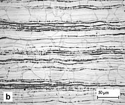
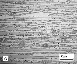
Figure 2b is a cross section from a weld joint of Carbon-Mn steel and duplex stainless steel. Similar to the weld in the CS-AS combination, the weld profile is wider at the top and bottom than at the midsection on the DS side of the weld. No undercut was observed. The weld also qualified to the stringent B level of quality acceptance as per BS EN 13919 - 1. Distinct flow lines in the form of 'whirls' were observed in the top and bottom section of the weld. The 'whirls' are a result of the solidification fronts and are due to oscillations in the keyhole.
Microstructure:
When joining a stainless steel to a carbon or low alloy steel, the Schaeffler diagram (
Figure 3) may be used to estimate the weld metal microstructure
[4] . The diagram depicts the various phases (F - ferrite / A - austenite / M - martensite) that result in the weld metal. In order to obtain this, the nickel equivalent (%Ni + 35%C + 20%N + 0.25%Cu) and the chromium equivalent (%Cr + %Mo + 0.7%Nb) of the steels to be joined are determined. Based on dilution estimates, tie lines are drawn to determine the resultant phases. This diagram is valid for arc welding and is widely used to select a filler wire for specific combinations of base materials. When the diagram is applied to laser welding the 'austenite+ferrite area' (shown by the dark lines in
Figure 3) narrows and moves towards the origin due to the very high cooling rates
[12,13] . If arc welded, the combinations considered show that a significant quantity of martensite shall result in the weld. This increases the hardness and decreases the ductility of the welds.
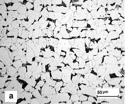
he microstructure of Carbon-Mn steel base material ( Figure 4a) exhibits small amount of pearlite in a ferrite matrix (white). The austenite grain boundaries can be seen in the microstructure of the AS base material (
Figure 4b) along with the strain lines that etch due to their lower corrosion resistance. The microstructure of the DS base material (
Figure 4c) consists of elongated austenite islands embedded in a ferrite matrix.
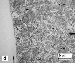
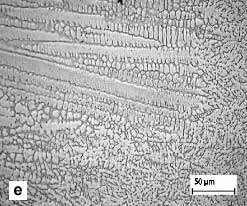
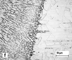
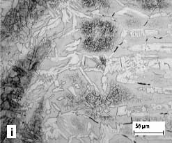
The microstructure of the CS to AS combination is shown in Figure 4def. The weld cap and root exhibited a relatively coarse dendritic structure. The weld centre ( Figure 4e) consisted of cellular austenite with some areas of lacy delta ferrite. The directionality of the dendrites can be attributed to the heat flow patterns. Most of the heat from the root tends to be dissipated through the width of the plates. This results in columnar grain growth towards the centre of the weld. Close to the fusion boundary on the CS side ( Figure 4d), some distributed pearlite was observed in a ferrite matrix. However on the AS side ( Figure 4f), grain boundary ferrite oriented towards the weld centre was observed in an austenite matrix. With CO 2 lasers, other researchers [2,14] have also seen similar weld microstructures in ferritic to austenitic steel welds.
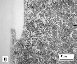
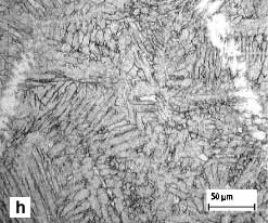
The microstructure of the CS to DS combination can be seen in Figure 4ghi. An austenite-ferrite structure that was predominantly ferrite with needle morphology was observed in the weld centre from top to bottom ( Figure 4h). More primary ferrite has resulted due to the extremely high cooling rates encountered. A distinct weld structure with pearlite in a austenite matrix was observed in the weld on the CS side ( Figure 4g). On the DS side of the weld ( Figure 4i), the austenite islands were discontinuous and a higher ferrite content was observed.
| |
| Fig.4a) C-Mn steel |
Fig.4b) Austenitic stainless steel |
 |
 |
| Fig.4c) Duplex stainless steel |
Fig.4d) Fusion boundary - C-Mn steel side, CS-AS weld |
 |
 |
| Fig.4e) Middle of weld, CS-AS weld |
Fig.4f) Fusion boundary - AS side, CS-AS weld |
 |
 |
| Fig.4g) Fusion boundary - C-Mn steel side, CS-DS weld |
Fig.4h) Middle of weld, CS-DS weld |
 |
 |
| Fig.4i) Fusion boundary - DS side, CS-DS weld |
|
 |
| Fig.4. Microstructures of the base materials and welds |
|
Fig.5. Hardness variation in the weld (taken at two sections) between:a) Carbon-Mn steel and austenitic stainless steel; b) Carbon-Mn steel and duplex stainless steel
Tensile testing:
Cross weld tensile testing was carried out on two representative samples from each weld as per BS EN 895. In all cases, failure occurred in the plain carbon steel parent material. The welds were thus deemed to be acceptable as failure has occurred in the lower strength material of the joint and not in the weld itself. The result obtained from tensile testing is in line with what was observed in hardness tests. The weld had higher hardness and was thus over-matched with regard to the mechanical strength characteristics. This result in turn is attributed to the fine transformed microstructure obtained due to the rapid cooling in laser welds.
Bend testing:
Side bend and face bend tests were conducted on samples from both weld combinations as per BS EN 910. 20 samples were tested in total. All samples passed the bend tests. This shows that the joint as a whole in both weld combinations exhibits good ductility.
The weld volume in laser welded samples is very low and conventional testing procedures may not be able to identify the effect of any small brittle zones formed. A detailed micro-hardness survey or use of miniature weld specimens for testing may be the way forward to test the properties of specific regions of a laser weld. This may be very time consuming and may not be the best solution in an industrial environment.
Conclusions
The following conclusions can be drawn from the work done:
- Autogenous transition joints between 6 mm thick sheets of C-Mn steel and austenitic stainless steel as well as C-Mn steel and duplex stainless steel have been produced with an Nd:YAG laser.
- In order to optimise the visual appearance of the joint, the laser beam was oriented towards the stainless steel (austenitic/duplex) part of the joint.
- Helium as a processing gas gave a better bead finish than nitrogen.
- Microscopy revealed distinct flow patterns in both welds. A dendritic structure with lacy ferrite was observed in the weld between C-Mn steel and austenitic stainless steel. A predominant ferrite structure with needle morphology was obtained in the weld between C-Mn steel and duplex stainless steel.
- In the CS-AS weld combination, higher hardness values have been measured in the top of the weld, while a less diverse hardness distribution was obtained in the CS-DS combination.
- Welds in both combinations were acceptable with regard to the mechanical properties requirements. Cross weld tensile tests resulted in fracture in the plain carbon steel. Side bend and face bend tests in both weld combinations passed the requirements.
A laser processing route for the manufacture of transition joints in dissimilar steels has been suggested. The advantages that this has over the traditional methods used are the elimination of the brittle zone formation, filler wire addition and the higher welding speeds together with minimum distortion. This could lead to potentially high cost savings in the relevant industry sectors. The manufacturing route could be exploited after conducting further studies (corrosion and in-service testing) on the welds produced.
References
- Lundin C D, Dissimilar metal welds - Transition joints literature review. Welding Journal. Vol. 61, No. 2, February 1982; pp 58s - 63s.
- Cam G, Yeni C, Erim S, Ventzke V, Kocak M, Investigation into properties of laser welded similar and dissimilar joints. Science and Technology of Welding and Joining. Vol. 3, No. 4, 1998; pp 177 - 189.
- Missouri S, Koerber C. Procedure development for improved quality single and dual LBW of dissimilar metals. Welding Journal, Vol. 77, No. 6, June 1998; pp 232s - 238s.
- Welding Handbook, Eight Edition, Vol. 4, Materials and Applications, Part 2, AWS, 1999.
- Parker J D, Stratford G C, Review of factors affecting condition assessment of nickel based transition joints. Science and Technology of Welding and Joining, Vol. 4, No. 1, 1999; pp 29 - 39.
- Sun Z, Moisio T, Effect of processing parameters on laser welded dissimilar steel joints. Welding Journal, Vol. 73, No. 4, April 1994; pp 63-70.
- Sun Z, Moisio T, Melting ratio in laser welding of dissimilar metals. Journal of Materials Science Letters, Vol. 13, 1994; pp 980-982.
- Guide to Engineering Materials: Advanced Materials & Processes, Vol. 156, No. 6, December 1999.
- Gunn R N: Duplex stainless steels - Microstructure, properties and applications, Abington Publishing, 1997.
- Kim J S, Watanabe T, Yoshida Y, Effect of beam-defocussing characteristics on porosity formation in laser welding. Journal of Materials Science Letters, Vol. 12, No. 22, 1995; pp 1624-1626.
- BS EN ISO 13919 - 1, Welding. Electron and laser beam welded joints: guidance on quality levels for imperfections. Part 1: Steel. 1997.
- David S A, Vitek J M, Hebble T L, Effect of rapid solidification on stainless steel weld metal microstructures and its implications on the Schaeffler diagram. Welding Journal, Vol. 66, No. 10, October1987; pp 289s-300s.
- ASM Handbook, Volume 6, Welding Soldering and Brazing, 1998.
- Sun Z, Fusion zone microstructures of laser and plasma welded dissimilar steel joints. Materials and Manufacturing Processes, Vol. 14, No. 1, 1999; pp 37 - 52.
Meet the authors
N C Sekhar joined TWI as Project Leader (Technical) in 1998. He is currently pursuing a Ph.D at the Department of Materials Science & Metallurgy, University of Cambridge, Cambridge, UK. At TWI he was involved in the development of procedures for welding and cutting of ferrous and non-ferrous alloys using Nd:YAG lasers. He was active in the application of the developed procedures to the industrial context.
J D Russell has recently left TWI to set up a consultancy in laser and electron beam processing. Whilst at TWI he held various positions including Head of the Departments concerned with these processes. He has over 30 years experience in the development and application of laser and electron beam welding.
Norman McPherson is currently Welding Engineering Manager for the Govan and Scotstoun shipyards of BAE Systems. He graduated from the University of Strathclyde with B.Sc. and Ph.D. degrees in metallurgy, and then joined British Steel at their Ravenscraig Works where he worked on the development of continuous casting, steelmaking and secondary steelmaking. This was followed by 4 years at Thor Ceramics, before he joined Kvaerner at Govan as Quality Manager in 1990.