Analysis of Limit Load for Embedded Flaws in Pipeline Girth Welds. Part I: Review and Validation of Current Procedures
Isabel Hadley*, Tyler London*, Mohamad Cheaitani+
TWI Ltd. Great Abington, Cambridge, UK
Presented at ESIA13, 13th International Conference on Engineering Structural Integrity Assessment, 19 and 20 May 2015, Manchester, UK
The use of engineering critical assessment (ECA) to derive flaw acceptance criteria for welded joints allows the maximum tolerable size of planar flaws to be determined on a fitness-for-purpose basis.
This paper concerns the calculation of the reference stress (or limit load) for use in ECA of circumferential embedded (buried) flaws in pipes. Analysis of this type of flaw presents particular problems. First, the ECA procedures most commonly used in the UK (R6 and BS 7910:2013) do not specifically address plastic collapse of circumferential flaws in pipes. Second, there is a known anomaly within the BS 7910 solution that results in critical flaw sizes apparently being smaller for embedded flaws than for surface-breaking flaws of equivalent size. This is usually resolved by the use of an engineering approximation to the published solution.
The paper summarises the analytical limit load solutions available in R6 and BS 7910 for embedded flaws in plates. A comparison of the R6/BS 7910 solutions with those derived from finite element analyses (FEA) of a 400mm OD pipe containing a range of circumferential flaws is also made. Finally, these ‘J‑based’ solutions are compared with analytical solutions and engineering approximations.
A companion paper (London and Hadley [1]) describes the derivation by FEA of limit load solutions for a second (914mm OD) pipe, and comparison of the results with experimental behaviour.
1. Introduction
The use of engineering critical assessment (ECA) to derive flaw acceptance criteria for welded joints allows the tolerability of planar flaws to be determined on the basis of fracture mechanics. A typical ECA involves assessing the significance of flaws with regard to failure mechanisms, including fracture, which the structure may experience during installation and operation.
The most commonly used approach to assess likelihood of fracture in metallic structures containing flaws is the failure assessment diagram (FAD), which requires the calculation of a plastic collapse parameter (Lr) and a fracture parameter (Kr). The plastic collapse parameter characterises the proximity to failure by yielding mechanisms and is defined as either a ratio of the applied load to the limit load, or equivalently, the ratio of the reference stress to the yield strength. The fracture parameter characterises the proximity to brittle or ductile fracture. The relationship between the parameters Lr and Kr is given by a Failure Assessment Line (FAL), the form of which allows the user to calculate Kr using linear elastic fracture mechanics concepts only, the shape of the FAL accounting for plasticity effects. The original FAL (Ainsworth [2]) removed the material dependence of the relationship between Kr and Lr by the choice of a suitable collapse load.
The work described here concerns the calculation of the reference stress (or limit load) for fracture assessments of circumferential embedded (buried) flaws in pipes. Flaws of this type (caused, for example, by lack of sidewall fusion during girth welding) are of considerable practical importance in pipeline construction and operation, but their analysis presents particular problems because of anomalies in some of the most widely-used assessment procedures. First, ECA procedures such as R6 [3] and BS 7910 [4] do not specifically address plastic collapse of embedded circumferential flaws in pipes. Second, there is a known anomaly within the BS 7910 solution that results in critical flaw sizes apparently being smaller for embedded flaws than for surface-breaking flaws of equivalent size. This is usually resolved by the use of an engineering approximation to the published solution for a flat plate, but could equally well be addressed by direct FEA of a cracked body, or by deriving pipeline-specific analytical solutions from FEA of a series of cracked bodies. A programme of work by Cheaitani and Goldthorpe [5, 6, & 7] has derived pipeline-specific J-based limit load solutions for a series of pipes containing circumferential embedded flaws, but the results have not hitherto been incorporated into any ECA procedures, and part of the remit of this work was to explore the applicability of their work to future editions of R6 and BS 7910. This paper includes:
- A summary of the analytical equations available in R6 and BS 7910 for analysis of plastic collapse of plates containing embedded flaws.
- A review of a TWI project aimed specifically at analysing plastic collapse for embedded circumferential flaws in pipes, using FEA and a J-based FAD.
- A comparison between the results of FEA and the use of analytical solutions from R6 and BS 7910.
- A discussion of the implications of using engineering approximations to the analytical solutions.
- A companion paper [1] describes the derivation of limit loads by FEA for a separate (914mm OD) pipe. Results from the FEA are then compared with experimental results from a programme carried out in Canada in the 1980s.
2. Review of analytical reference stress/limit load solutions
None of the commonly-used ECA procedures addresses limit load/reference stress solutions specifically for embedded circumferential flaws in pipelines. Solutions are given instead for embedded flaws in flat plates, as outlined below (further details are given in Hadley and London [8]).
2.1 R6
Section II.4 of R6 [3] discusses plastic limit load analysis. It notes that, although there may be only one KI solution per geometry, there may be several for limit load. For example, there will be different solutions depending on whether the cracked body is under plane stress or plane strain conditions, and whether the Tresca or von Mises yield criterion is used. The limit load will also depend on whether a ‘local’ or ‘global’ yield criterion is assumed.
A plane stress limit load is normally recommended for a conservative approach, since the plane stress limit load is lower (and Lr therefore higher) than the limit load for plane strain conditions. Users are referred to section IV.1 (compendium of limit load solutions) and to a number of external sources, but a warning is given against choosing a solution from the literature, because of the high variation between published solutions for a given geometry.
A further distinction is made between ‘local’ and ‘global’ collapse adjacent to surface‑breaking and embedded flaws. Whereas the global solutions relate to overall collapse of the structure (assuming elastic-perfectly plastic material behaviour), the local solutions envisage yielding of the ligament, and may tend to zero for near-surface defects. Local yielding does not necessarily lead to a failure condition, of course, although it may be treated as such for the purposes of an ECA. The local limit load is, in general, lower than the global limit load. R6 also recommends the use of detailed analysis to calculate limit load (eg a J based limit load) in order to reduce the conservatism associated with the use of a local limit load and to explore the relevance of using a global limit load instead.
The limit load solutions can be found in full in sections IV.1.6.3-1 and IV.1.6.3-2 of R6. They are presented in the form of a parameter nL, which equates to the ratio of the limit load of the flawed section to that of the unflawed section. The approach used to develop these solutions is described by Lei and Budden [9].
2.2 BS 7910
BS 7910 [4] expresses plastic collapse in terms of reference stress rather than limit load. Equations for reference stress adjacent to an embedded flaw in a plate are given in Sections P.6.3 and P.6.4 of the standard. BS 7910 contains a single solution, based on a combination of analytical and experimental work by Willoughby and Davey [10]. They expressed failure load as a function of an effective flaw size parameter α’’ derived from flaw height (2a), flaw length (2c), section thickness (B) and plate width (W):
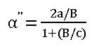
for W≥2(c+B), ie where the flaw is small compared with the plate width
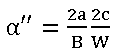
for W<2(c+B), ie where the flaw is large compared with the plate width
Figure 1 shows an example of the experimental data from [10]. The failure conditions for flat plates containing artificial embedded flaws are compared with the analytical solutions for plastic collapse in R6 and BS 7910. It can be seen that, for this particular case (a plate in pure tension), the BS 7910 solution is equivalent to the R6 solution for global collapse under pin-jointed conditions. It is also apparent that the trend in experimental results can be represented by a simple offset to the BS 7910/R6 global pin‑jointed solutions. A full analysis of this work (see [8] for details) shows that, as the burial depth (p/B) of the flaw increases, so the distinction between the different solutions (local and global, pin-jointed and fixed restraint) decreases and all solutions converge to represent a simple loss of area model.
Although the BS 7910 equations are extensively used for the analysis of embedded flaws in pipeline girth welds, the approach presents certain anomalies. A surface-breaking flaw of length 2c and height as experiences higher crack driving force (KI) than does an embedded flaw of similar size (length 2c and height 2ae). However, because the reference stresses for the surface-breaking and embedded flaws were derived from different assumptions (rigid restraint in the case of a surface flaw, pin-jointing for the embedded flaw), the reference stress calculated for an embedded flaw may be higher than that for a surface breaking flaw having the same length and height and subjected to the same loading conditions, with the result that the maximum tolerable flaw size for an embedded flaw is apparently smaller than that for a surface-breaking flaw under similar levels of loading.
To quote Willoughby and Davey [10] ‘...For long embedded flaws in tension, the assumption of pin jointing is not excessively conservative, and is preferred because of the simplicity of the resulting solutions, compared to that for rigid restraint.’ Given that the emphasis at the time of their work was principally on avoidance of failure rather than on defining the safety margin against failure, or on calculating maximum tolerable flaw size, the fact that the safety factor varied between the solution for an embedded flaw and that for a surface breaking flaw would not have been considered a serious drawback. Nowadays, ECA is being systematically applied as part of the design process, linked to NDT requirements and structural reliability concepts, so there is an increasing need to refine the calculation of reference stress for embedded flaws.
2.3 Engineering approximations to the BS 7910 approach
In practice, the anomaly in the calculation of reference stresses for surface breaking and embedded flaws can be addressed in various ways. For example, in Appendix A of DNV‑OS-F101 [11] (a pipeline-specific ECA appendix based on BS 7910), the advice given (clause 102) is that ‘…it is acceptable to only assess surface breaking flaws and to regard the maximum allowable flaw heights assessed as valid also for embedded flaws with the same length’ (this applies if the ligament is greater than or equal to half the flaw height).
The practice adopted by the authors’ organisation is slightly different from this, and involves applying a correction factor between 0.9 and 0.95 to the reference stress calculated in accordance with BS 7910. The rationale for this is based on the different safety factors inherent in the reference stress solutions for surface and embedded flaws, as described in [8].
2.4 API-579-1/ASME-FFS-1-2007
This procedure [12] is widely used in the USA, in particular for assessment of in-service damage in the refining and petrochemical industries, and more recently in the fossil power industry. The so-called Level 3 procedures are based on fracture mechanics and have a similar technical basis to the BS 7910 and R6 procedures, albeit with a different user base in mind. For embedded circumferential flaws in pipelines, API-579-1/ASME-FFS-1-2007 [12] recommends the use of the solution derived by Willoughby and Davey [10], ie the same solution as that used in BS 7910.
3. FEA Modelling of circumferential embedded flaws in pipes
3.1 Introduction
Aware of the shortfalls in the approaches adopted by current ECA procedures, Cheaitani and Goldthorpe [5, 6, & 7] carried out numerical modelling of a series of pipes with a range of materials properties and geometries. Embedded flaws of various sizes and positions were modelled, and a pure remote bending moment applied to represent conditions of pipeline installation. The objective of the work was to derive J-based limit loads (see [1] for definitions and further details) for a range of flaw sizes/positions, and ultimately to derive parametric solutions that could be incorporated into future analytical flaw assessments. Given such a pipe-specific solution, the user would not need to define the boundary conditions (fixed grip or free rotation, local or global collapse) and therefore would not need to choose between the various formulations for flaws in flat plates currently available in R6 or BS 7910.
3.2 Method
Because of the fact that pipeline installation sometimes involves loading well beyond the conventional definition of the yield strain (ie beyond a total strain of around 0.5%), simulations were carried out for gross strains of up to around 1% strain. The particular analyses considered in this work, however, are those corresponding to a total applied strain of 0.5%, ie at around the limit of elasticity.
The J-based limit load determined in this work was defined as the limit load that, when used to determine J via a FAD-based assessment would give the same value of J as the value determined from FEA. Two particular sets of results are presented in this section:
- Method based on elastic bending stress: elastic driving force Je was derived from elastic pipe bending stress and the limit load derived on the basis of an Option 2 FAD.
- Method based on elastic-plastic bending stress: driving force Jep was derived from elastic-plastic pipe bending stress and the limit load derived on the basis of an Option 2 FAD.
The J-based limit loads were found to vary with applied load (bending moment) and strain level (typically increasing with Lr and remote applied strain). Cheaitani and Goldthorpe [5] report that this load-dependence can be largely overcome if the J-based limit load for a given load level is multiplied by the ratio of elastic-plastic pipe bending stress to elastic pipe bending stress, i.e. the resulting parameter is largely independent of load level (for Lr > 1 and strain > 0.3%). Consequently, they propose that if the J-based limit load is known at a given Lr or applied strain, it can be estimated with reasonable accuracy at some other applied Lr or applied strain values.
Results were also expressed in terms of the ratio of J-based reference stress to Pm, the elastic-plastic pipe bending stress. This ratio is inversely proportional to the abovementioned parameter (product of limit load and ratio of elastic-plastic pipe bending stress to elastic pipe bending stress) and consequently is largely independent of applied load.
Of particular interest to this work are the series of calculations carried out on a single pipe geometry (400mm OD x 20mm WT) assuming a particular materials model (continuously yielding behaviour, as described by a Ramberg Osgood (RO) equation);
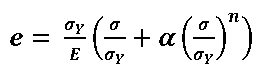
(1)
Here, e represents strain, σY represents the 0.2% offset yield strength (400N/mm2) and the work hardening coefficient n=15. The 0.2% offset strength is very close to the value of stress at a total engineering strain of 0.5% (σt0.5%); indeed σt0.5% is often used as a proxy for σY in the linepipe industry.
These models contained embedded flaws with ligament heights (p) of between of 1.5 and 6mm from the inner surface (most cases used p=3mm), flaw heights (2a) between 3 and 9mm, and lengths (2c) between 25 and 250mm. Details of the pipe and flaw geometries are shown in Table 1. Reference [5] presents the results in terms of a J-based limiting moment, the ratio σref/Pm (ratio of reference stress to gross elastic-plastic applied bending stress) and non-dimensional limit load (ratio of the limit moment for a flawed section to that for an intact section, ie equivalent to nL in R6 terminology). Extracting just those values corresponding to a global total strain of 0.5%, very close to the 0.2% offset strength, we can compare the FEA results with those of R6 and BS 7910 (Figure 2 to Figure 4). Since BS 7910 and R6 contain solutions for flat plates only, the results shown have to invoke some assumption about the plate, which was assumed to be half of the mean circumference for the purposes of these calculations. The x-axis, α’’ represents the equivalent flaw size parameter, as defined in BS 7910, and the numbers above each datapoint correspond to the model number as defined in Table 1.
TABLE 1 - Selected examples of pipe models formulated by Cheaitani and Goldthorpe [5]
| Model no. |
Pipe OD, mm |
Pipe WT, mm |
Flaw height, 2a, mm |
Flaw length, 2c, mm |
Ligament to ID (p1), mm |
Ligament to OD (p2=B-2a-p1), mm |
| 1 |
400 |
20 |
3 |
50 |
1.5 |
15.5 |
| 10 |
400 |
20 |
6 |
50 |
1.5 |
12.5 |
| 2 |
400 |
20 |
3 |
50 |
3 |
14 |
| 3 |
400 |
20 |
3 |
50 |
14 |
3 |
| 6 |
400 |
20 |
6 |
50 |
3 |
11 |
| 8 |
400 |
20 |
9 |
50 |
3 |
8 |
| 11 |
400 |
20 |
3 |
25 |
3 |
8 |
| 12 |
400 |
20 |
3 |
100 |
3 |
14 |
| 13 |
400 |
20 |
3 |
200 |
3 |
14 |
| 14 |
400 |
20 |
3 |
250 |
3 |
14 |
| 15 |
400 |
20 |
6 |
25 |
3 |
11 |
| 16 |
400 |
20 |
6 |
100 |
3 |
11 |
| 4 |
400 |
20 |
3 |
50 |
6 |
11 |
| 5 |
400 |
20 |
3 |
50 |
9 |
8 |
| 9 |
400 |
20 |
6 |
50 |
6 |
8 |
| 17 |
400 |
20 |
3 |
25 |
6 |
11 |
Figure 2 (two results only) shows the trends for flaws close to the inner surface of the pipe (p=1.5mm), whilst Figure 3 shows the results from ten models in which the ligament height, p, is 3mm. Most models within this set are intended to represent flaws that are located approximately one weld bead height above the inner surface of the pipe. Model no. 3, conversely, is assumed to have a flaw located 3mm from the outer surface, and is analogous to model no. 2 in all other respects. Figure 4 shows the results for models in which the flaw is located 6mm from the inner surface (outer surface in the case of model no. 5, which is otherwise the same as model no. 4).
These results show the tendency for the solutions to diverge most at higher values of α’’ and when the depth of burial (p/B) is small, where the distinction between global and local solutions is most significant. The trends shown are broadly in line with the advice given in R6, ie that global limit loads exceed the local, with fixed grip solutions predicting higher limit loads than do solutions based on pin-loading. Treating the FEA results based on elastic plastic stress analysis as the benchmark (see solid lines), it can be seen that the R6 ‘global’ results (for both fixed-grip and pinned conditions) lie above the FE results, ie use of these formulations for the pipes considered would be non-conservative and potentially unsafe. All other equations (the R6 ‘local, fixed’, R6 ‘local, pinned’ and BS 7910) are conservative in most cases, with the R6 ‘local, pinned’ equation the most conservative.
Several additional trendlines have been added to Figure 3; this represents a geometry that is of practical importance and thus has the largest number of analyses (ten) associated with it. As well as the R6, BS 7910 and FEA solutions, the figure shows the results of:
- Applying a ‘safety factor’ (actually a reference stress reduction factor) of 0.90 or 0.95 (see points labelled ‘SF=0.9’, ‘SF=0.95’) to the BS 7910 reference stress solution for an embedded flaw, thus replicating the practice used by TWI and referred to earlier. This is equivalent to multiplying the Pm/σref ratio by 1.11 or 1.05.
- Applying a safety factor of 1.1 or 1.15 to the R6 global collapse solution for an embedded flaw, as suggested by Cheaitani and Goldthorpe [5] (see points labelled ‘SF=1.1’, ‘SF=1.15’). The fixed-grip solution is used to illustrate this case, as it predicts higher collapse loads than does the pin-jointed solution.
- Treating the flaw as an internal surface-breaking flaw with height (as) equal to the height (2ae) of the embedded flaw, to represent the recommendation given in the 2013 edition of DNV-OS-F101 [11] (see points labelled ‘DNV’). The Kastner collapse solution is used in this case, since this is the recommended practice in DNV-OS-F101 [11]. [The exception to this was analysis no. 3, which represents an embedded flaw 3mm from the outer surface. This was therefore treated as an external, rather than internal, surface flaw].
Most of the analysis points generated by the first approach lie below the results from FEA (shown as a solid line), and can thus be considered safe. However, the margin of safety is small (or even below 1) for small flaws, increasing as the flaw size increases. Consequently, a reference stress reduction factor of 0.95 appears to be more appropriate for small flaws, with a factor of 0.9 for larger flaws. The simplified practices adopted by TWI are therefore largely supported by this work.
The approach suggested by Cheaitani and Goldthorpe [5] (item 2 above) is that the R6 global collapse loads should be divided by a safety factor of between 1.10 and 1.15. Using a safety factor of 1.15 produces a series of points below the trendline for the FEA and is therefore safe for the case examined, albeit with a slightly variable safety margin. Using a safety factor of 1.1 produces points close to or below the FEA results, and captures the trend of the FE results reasonably well.
Use of the Kastner solution, as recommended by DNV (item 3), produces collapse loads above the trendline shown for the FEA results. In terms of plastic collapse analysis alone, treating embedded flaws as surface-breaking flaws of the same dimensions is therefore seen to be ‘unsafe’; however, overall defect-tolerance depends not only on Lr but also on Kr. Whilst the DNV approach appears to overestimate the limit load (and thus to underestimate reference stress and Lr), it also overestimates the crack driving force KI, by treating embedded flaws as if they were surface-breaking. These two effects may in practice cancel each other out, although detailed consideration of this phenomenon is outside the scope of the current study.
Given that deriving limit load solutions on a case-by-case basis from direct FEA of a cracked body is a laborious process (particularly when considering crack growth, for example due to fatigue), Cheaitani and Goldthorpe [5] also developed a parametric equation for the limit moment at an applied strain of 0.5%, calculated from geometrical parameters only, using elastic driving force, Je, derived from the elastic pipe bending stress. This is given in full in the original reference, and included in Figure 3 (see points labelled ‘parametric equation’). Whilst this is derived from FE models and thus applicable only within the range for which the models were developed, it does allow a comparison between the FEA results and the R6/BS 7910 solutions within the pipe size range for which the FEA calculations were carried out. Figure 2 to Figure 4 compare the solutions, from which it can be seen that the FEA solutions (and the parametric solutions derived from them, shown in Figure 3 only) lie somewhere between the equations for local collapse (the BS 7910, R6 ‘local, fixed-grip’ and R6 ‘local, pinned’ and those for global collapse (R6, ‘global, fixed’ and R6 ‘global, pinned’). This observation is consistent with the approach on which the parametric equation is based: it represents plastic collapse conditions (and corresponding load-bearing area) that lie between the conditions that apply to global collapse and conventionally-defined local collapse (the latter assumes that the load bearing area extends one plate thickness at either side of the flaw).
Finally, the effect of ligament height on the limit load solution is summarised in Figure 5, which shows how limit load increases with increasing depth of burial of the flaw.
4. Discussion
The equations given in BS 7910:2013 for plastic collapse around embedded flaws, due to Willoughby and Davey [10], have remained unchanged since the 1991 edition of PD 6493, the forerunner to BS 7910. Their limitations, in particular the fact that the assumption of pin jointing led to a more conservative assessment than the equivalent calculation for surface‑breaking flaws, were recognised from the outset. However, given that the predominant role of PD 6493 at that time was the safe sentencing of fabrication flaws that had failed to meet workmanship criteria (rather than defining margins against failure), this was not seen as a major drawback. Given that BS 7910 is increasingly used in areas such as the design of welded joints, and in failure analysis, there are many occasions where an alternative, more accurate, solution is desirable.
R6 provides a range of different solutions for plastic collapse around embedded flaws, depending on whether the collapse behaviour is considered to be ‘local’ (restricted to the ligament adjacent to the flaw) or ‘global’ (spread across the whole cross-sectional area of the unflawed ligament). Depending on the restraint against bending, different formulations for ‘fixed grip’ and ‘pin-jointed’ boundary conditions may also apply. However, there is a large difference between the formulae given in the R6 compendium, and it can be difficult for the analyst to decide which set of boundary conditions is appropriate for a given loading scenario.
An obvious alternative is to model the cracked structure directly using FEA, and to derive a J-based limit load. This paper outlines a programme of work aimed at achieving this for the specific case of embedded flaws in pipes. The results of this programme have already been reported in detail, but selected results have been extracted for the purposes of the current project, and results compared with those derived from the parametric equations in R6 and BS 7910:2013.
Finally, the use of three engineering approximations based on analytical formulae for plastic collapse around embedded flaws has been considered:
- Use of the BS 7910 reference stress solution, multiplied by a correction factor of 0.9 or 0.95: this reduces the value of Lr relative to the value obtained directly from the published standard, and safely predicts the trends shown in Figure 3 except for the very smallest flaws. Ideally, the correction factor should vary with flaw size (0.95 for small flaws, 0.90 or lower for larger flaws), since the BS 7910 solution diverges from the ‘benchmark’ FEA solution for large flaw sizes. However, the method is in general safe.
- Use of the R6 solution for global collapse under fixed-grip conditions, with the limit load divided by a safety factor of between 1.1 (mostly safe) and 1.15 (always safe): this is, of course, equivalent to multiplying the reference stress by a factor 1.1-1.15 (although the R6 compendium is couched in terms of limit load rather than reference stress), and fits the trend of the analyses shown in Figure 3 quite well.
- Treating the embedded flaw as a surface-breaking flaw of equivalent dimensions as recommended by DNV-OS-F101. Given that the current recommendation is to use the Kastner equation for calculation of reference stress, this advice errs on the side of non-conservatism in the calculation of Lr (see Figure 3), although this may in practice be balanced by conservatism in the calculation of Kr. [It should be noted that earlier editions of DNV-OS-F101 advised the use of a flat plate solution for calculation of reference stress, which would have given the same result as the R6 ‘local, fixed-grip’ solution].
5. Summary and Conclusions
Plastic collapse (or limit load) solutions for embedded circumferential flaws in pipes have historically been derived from analytical solutions for flat plates, and incorporated into flaw assessment procedures, including R6 and BS 7910. However, a range of solutions is available in R6 (for fixed-grip or pin jointed restraint conditions, and for global or local collapse), and it is rarely obvious which is the most appropriate to use for a particular case.
Various engineering approximations have been proposed based on the limit load/reference stress solutions in R6 and BS 7910. These include applying a safety factor (>1.0) to the (R6) global limit load solution, applying an ‘enhancement factor’ (>1.0) to the BS 7910 reference stress solution (equivalent to applying a safety factor of <1.0 on the limit load solution), or treating the embedded flaw as if it were actually surface-breaking (DNV OS F101). Hitherto, these approximations have not, to our knowledge, been calibrated against experimental results or numerical analyses.
An alternative to the calculation of limit load/reference stress is to use Finite Element (FE) Analysis. The J-based approach requires direct elastic-plastic FE modelling of a flawed component. The Option 3 FAD produced by FEA is then matched to the Option 1/Option 2 FAD as defined in R6 and BS 7910.
An earlier study of J-based limit loads in embedded circumferential flaws in 200mm OD pipes subjected to global bending was re-examined in order to compare the results with code-based approaches (R6, BS 7910, DNV-OS-F101 [11] Appendix A) and engineering approximations based on the codes. This showed that the difference between the available approaches:
- Increases as the flaw burial depth, p, approaches zero (ie for deeply buried flaws there is relatively little difference between the equations).
- Increases as the relative flaw size, α’’, increases.
The re-examination of Cheaitani and Goldthorpe’s study [5] also revealed some parametric formulae for limit load to be potentially unsafe, unless a safety factor is applied: these include the R6 global solutions for both fixed-grip and pin-jointed conditions and the DNV-OS-F101 [11] solution (which is actually based on the assumption of a surface-breaking flaw in a curved shell). Conversely the BS 7910 solution and R6 local pin-jointed collapse solution were shown to be very conservative (excessively conservative solutions such as these can be ‘tuned’ by applying a correction factor as described in item 3 above).
6. Acknowledgements
This publication is based on work carried out by TWI on behalf of the R6 panel, described in full in Hadley and London [8].
7. Reference list
- London and Hadley, Analysis of limit load for embedded flaws in pipeline girth welds, Part II: Development and validation of new FEA models, this conference.
- Ainsworth R A, Engineering Fracture Mechanics, The assessment of defects in structures of strain hardening material, 19 633-642, 1984.
- BEGL, R6 Revision 4 and amendments, Assessment of the integrity of structures containing defects, British Energy Generation Ltd, Gloucester, UK (Amendment issued in subsequent years), 2001.
- BSI, Guide to methods for assessing the acceptability of flaws in metallic structures, British Standards Institution, BS 7910:2013, 2013.
- Cheaitani M J and Goldthorpe M R, Reference Stress and J-based Limit Load for Circumferential Embedded Flaws in Pipe Girth Welds, Abington Hall, United Kingdom, TWI Member Report 921/2009, (http://www.twi-global.com/technical-knowledge/industrial-member-reports/reference-stress-and-j-based-limit-load-for-circumferential-embedded-flaws-in-pipe-girth-welds-921-2009/), 2009.
- Cheaitani Mohamad J, Journal of Pipeline Engineering, Approaches for determining limit load and reference stress for circumferential embedded flaws in pipe girth welds, 8/8, Q3, (http://www.twi-global.com/technical-knowledge/published-papers/approaches-for-determining-limit-load-and-reference-stress/), 2009, pp. 149-166.
- Cheaitani Mohamad, J-based Limit Load and Reference Stress for Circumferential Embedded Flaws in Pipe Girth Welds, Pipeline Technology Conference, Ostend, Belgium, 12-15 October 2009.
- Hadley I and London T Assessment of limit loads in circumferential embedded flaws in pipes, TWI Report 23887/2.1/15, January 2015
- Lei Y and Budden P J, International Journal of Pressure Vessels and Piping, Limit load solutions for plates with embedded cracks under combined tension and bending, Vol 81, 2004, pp 589-597.
- Willoughby A A and Davey T G Plastic collapse at part wall flaws in plates, Wei, RP, ed. Fracture mechanics: perspectives and directions. Proc. 20th national symposium. STP 1020. Bethlehem, PA, June 23-25 1987, 1989.
- DNV-OS-F101 Submarine pipeline systems (http://www.dnv.com) 2013.
- API/ASME, API-579-1/ASME-FFS-1-2007 Fitness for service, API 579 Second Edition, American Petroleum Institute (API)/American Society of Mechanical Engineers (ASME) 2007.
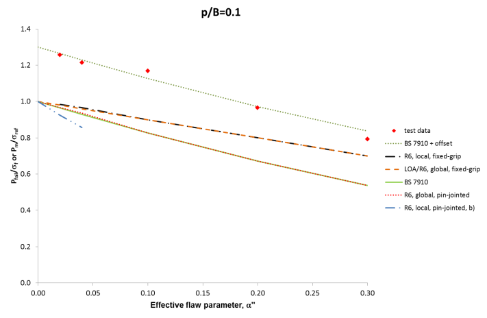
FIGURE: 1 - Results of tests on plates containing embedded flaws [10], and a comparison with various models of plastic collapse: p/B=0.1, ie near-surface flaws.
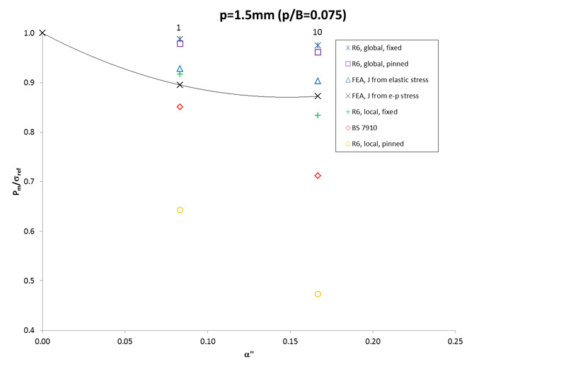
FIGURE: 2 - Comparison of the analyses carried out by Cheaitani and Goldthorpe [5] with closed form solutions from BS 7910 and R6; flaws buried 1.5mm from the surface (p/B=0.075).
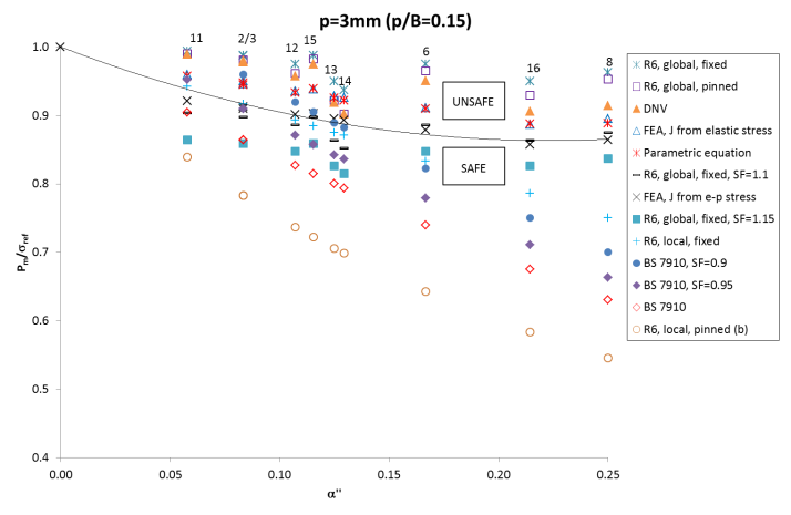
FIGURE: 3 - Comparison of the analyses carried out by Cheaitani and Goldthorpe [5] with closed-form solutions from BS 7910 and R6; flaws buried 3mm from the surface (p/B=0.15).
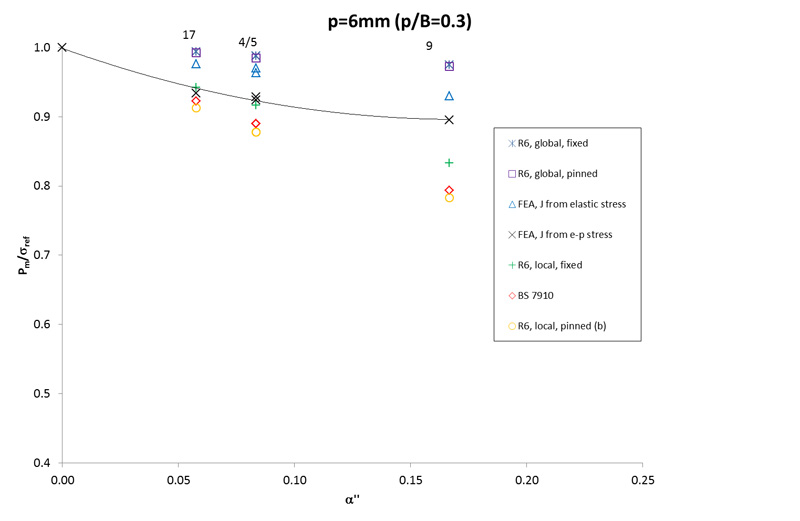
FIGURE: 4 - Comparison of the analyses carried out by Cheaitani and Goldthorpe [5] with closed-form solutions from BS 7910 and R6; deeply buried flaws (p/B≥0.3).
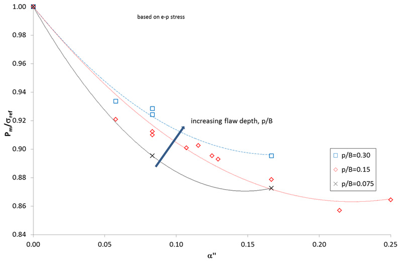
FIGURE: 5 - Effect of burial depth (p/B) on limit load solutions derived by Cheaitani and Goldthorpe [5]