Paul Hilton and Lien Nguyen
A new method of laser beam induced surface modification using the Surfi-Sculpt process (April 2008)
Paper presented at 3rd Pacific International Conference on Applications of Lasers and Optics, PICALO, 16-18 April 2008, Beijing China, paper 201.
"A new method of laser beam induced surface modification using the Surfi-Sculpt® process," paper 201, PICALO 2008 Proceedings. Copyright 2008, Laser Institute of America. All rights reserved. The Laser Institute of America disclaims any responsibility or liability resulting from the placement and use in the described manner.
Abstract
Surfi-Sculpt® is a power beam process, invented at and patented by TWI, which enables controlled surface features to be developed on a range of substrates, including but not limited to metals, polymers and ceramics. Such surface features were first demonstrated using electron beams, employing electromagnetic coils to first focus the beam and then deflect this focused beam over the material surface in a rapid and controlled manner. This paper will describe more recent work, which has involved the use of focused laser beams to develop similar features. Fibre delivered laser beams and galvanometer driven scanning mirrors have been used to produce the rapidly moving spot of laser energy required for the process. After generation of a molten pool in the substrate material, the beam is then rapidly moved relative to the work-piece. This, as a result of vapour pressure and surface tension effects, leads to material being moved from within the pool to regions at the extreme end of the beam movement. By repeating this process, it is possible to build up protrusions of several millimeters in height above the surface of the material. By combining and sequencing these protrusions together, a variety of shapes or features can be formed. The laser experiments have been performed in air and in various gaseous environments and, for comparison purposes, with electron beam work, in vacuum. The technique is not limited to the production of protruding surface features but can also be used to modify the structure deeper within the work-piece, so as to effect modification in the bulk substrate, for example, by way of the creation of deep holes in the material. The features created using the Surfi-Sculpt technique offer technical advantages and commercial opportunities in a wide range of industry sectors.
Introduction and scope of work
Power beams have been used for many decades to process metals in a variety of ways, including welding, cutting and drilling. This paper describes a new laser variant of a technique that uses power beams to melt and displace material, thereby creating a surface form. The material moves largely due to surface tension generated by a temperature gradient created across a molten material surface. How the material moves, and ultimately the shape of the features produced, can be determined by precisely controlling the beam path and speed over the surface. The process can create surfaces that may be impossible to produce by other means. Using electrons as the power beam source, a large number of features of a few millimetres height above a metallic surface have been fabricated in a very rapid way - several thousand features within 10 seconds. Recent electron beam developments have also demonstrated that the technique can work over a wide dimensional scale: making small features of tens of microns in size, and at the other extreme creating protrusions of tens of millimetres diameter and height.[1-4] The types of surfaces produced are being investigated for many applications, including orthopaedic implants, with improved fixation due to promotion of bone in-growth, preparations for metals to be joined to composite, and for making surface features that enhance thermal transfer for high performance heat exchangers.
Figure 1 shows a schematic representation of how the process works when a high intensity laser beam is passed over the surface of a metal plate several times.
Fig.1. Schematic of the process involved in the generation of a Surfi-Sculpt like feature. Note the direction of the beam movement is from right to left
Although most of the work to date has used electron beams, which are readily manipulated using electromagnetic deflection systems, the work reported here has employed high brightness laser beams, with either rapid work piece movement or galvanometric mirror beam deflection.
Equipment and experimental procedures
The electron beams used for this process are bright, in terms of power density in the focus/per steradian of solid angle in the focusing beam, and move at very high speeds, by virtue of electromagnetic deflection under computer control. Recently, developments in high power laser sources and galvanometric deflection of the resulting high power laser beams, have made it possible to demonstrate Surfi-Sculpt features on both metals and plastics using laser beams. Two axis galvanometer driven mirror based scanning systems have been used for many years in the application of laser marking. This is the largest industrial use of lasers for materials processing, and it is highly likely that anything you might pick up today, which includes a permanent mark, has been processed using a laser. The software for these systems is very advanced and character writing speed, for example, can be as high as up to 1000 characters, in some materials. In addition, the galvanometers can scan the laser beams at speeds in the region of a few metres per second, similar to the speeds used for electron beam processing. Higher power variants of these devices have appeared recently, targeted at what the laser processing world terms 'remote' welding applications. In these applications, a high power laser beam is scanned across the surface of metals to produce stitch welds. A successful example of this is for the joining of pressed metal forms to construct the inner assemblies of car doors.
Currently, all laser beams used for materials processing applications which involve the generation of heat (there are some that allow for cold machining) need to be focused to produce the required power densities. This focusing laser beam passes through the galvanometer mirror system and clearly, as the deflection angle increases, the focus position (on a flat sample) would change. To alleviate this problem, special 'flat field' lenses have been developed to maximise the effective scan area of the moving beam. More recently, a third axis has been added to these systems, in that the beam focusing lens can be made to move along the beam axis in an adaptive way, thus allowing the computer control system to compensate for changes in focus position due to changes in beam deflection angle.
It is now quite commonplace to transmit several kilowatts of laser power down an optical fibre, only a few hundred microns in diameter. This capability is very useful in materials processing applications as it means the laser source can be positioned at any convenient location and the laser power simply transmitted down 'the optical highway' to the position it is needed. To use optical fibres, laser sources generating beams about 1µm in wavelength are most common for high power use. Two recent innovations in high power lasers which produce light which can be fed down optical fibres are the thin disc laser and the fibre laser. In the fibre laser, the lasing medium is an optical fibre doped with low levels of a rare-earth element, such as ytterbium, erbium or thulium, which determine the wavelength of the output light. Single-mode fibre lasers, of very high brightness, operating as individual units, have delivered around 3kW of power in laboratory conditions. Commercial units up to 2kW are available. Multi-mode fibre lasers are also available which combine together many single mode lasers of low power to produce powers as high (or higher) than20kW. Thin disk (or disc) lasers are solid state lasers, in which the lasing medium generally consists of a thin slice or disk of ytterbium-doped yttrium-aluminium garnet crystal. These lasers produce powers up to about 10kW with high beam quality.
In fact the main technical advantage of these two laser sources is their high beam quality and high brightness. This means the beams can be focused to small spot diameters, and a longer focal length lens can be used to focus a high beam quality laser beam, for a given spot size, when compared to that from a low beam quality laser. For the applications here, this is significant in that high beam quality is particularly attractive for processing with the type of scanning systems described above. In the results reported here, both disc and fibre lasers have been used at relatively modest laser powers of less than 2kW, in conjunction with two different laser beam scanning systems, both developed primarily with laser welding applications for the automotive industry in mind. The disc laser was manufactured by Trumpf and the fibre lasers by IPG Photonics and SPI Lasers. The scanning systems were manufactured by Trumpf and Arges. Some work was also undertaken with a stationary laser beam and sample manipulation using a 2 axis moving table manufactured by Anorad.
The initial laser work was undertaken in air, as the ability to work without the vacuum, normally required with any electron beam process, was seen as one of the major drivers for using lasers. Later a small chamber was built, which could be evacuated and also filled with an inert gas, and which contained a quartz window through which the focusing laser beam could be passed. This was used to investigate the effect of the environment surrounding the process on the forms produced. The metallic material used in the trials consisted of small plates of Ti-6Al-4V alloy. The plastic material consisted of small plates of black polyethylene. For both materials, initial work consisted of producing simple linear shapes, using a repeated 'swipe' of the focused beam across the surface of the material. The main process variables were laser power, swipe speed, swipe length and the dwell time between swipes. For both the Trumpf and IPG laser systems, the minimum focused spot size was estimated to be between 0.3 and 0.34 mm in diameter. For the SPI laser system, the minimum spot size was significantly smaller, however, this was used in a defocus condition for the trials on plastics. Subsequently, more complex shapes were attempted, by combining several single swipes together to form a pre-determined pattern.
Results
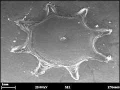
Figure 2 shows typical preliminary results of using a laser beam to generate a conical type Surfi-Sculpt feature in titanium plate, using a 'star' form for the swipe pattern (also shown in Figure 2). The sequence consisted of repeats of eight radially sequential single swipes. These results were obtained in air and did not use the vacuum normally required for electron beam work. The processing conditions are given in the figure caption. These conditions were determined from optimisation trials on single swipes. Initially the star shaped pattern was generated with no 'gap' in its centre. This condition resulted in a protrusion which was not particularly conical. The improved shape seen in Figure 2, was produced with a gap of about 1mm in diameter in the center of the pattern. High speed video of the process showed this to be beneficial to the cyclic nature of the build up of the material. It also indicated the possibility of the structure being hollow inside, at its base. Also seen in the SEM images are the swipe terminations and the slots below the surface, from which the material moved to make the protrusion. Clearly, several sets of this particular feature could be put together to form an array on the material surface. In this case the height of the protrusion was about 5mm, and its manufacturing time was about 5 seconds, using a laser power of about1kW.
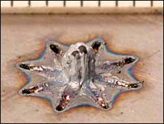
Fig.2. Photograph (a), diagram (b) and SEM images (c, d) of a conical feature created in air. The arrows in the diagram indicate the direction of the movement of the laser beam. The operating parameters were: laser power = 1 kW, scanning speed = 16 m/min, number of swipes per arm = 60, time delay between swipes = 0.5 ms. The total time required to create this star shape was approximately 5 s
It is very difficult to process plastic materials using electron beams and another driver for the laser work was to see if the process would work on plastic materials using laser beams. This has been demonstrated on polypropylene using a carbon dioxide laser source and on polyethylene, using the fibre laser source, although the only results shown here are for polypropylene. Black polyethylene readily absorbs the near infra red light of the fibre laser and to demonstrate the effects much lower laser powers (of the order 10W) were used. Figure 3 shows an attempt to reproduce the star shape shown in Figure 2, by keeping the beam stationary and manipulating the sample using a fast X-Y table. It can be seen that the process appears to work with plastics, notwithstanding the large difference in viscosity between molten plastic and molten metal. In Figure 3 it is believed the 'disruption' seen at the top of the cone is due to a programming error for the very last swipe, which appears to have been performed at a much lower speed, or possibly in reverse.
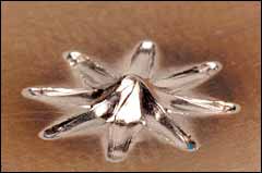
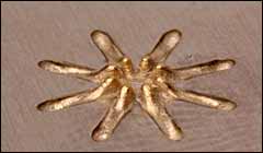
In order to study the effects of atmospheric condition in the processing region, for metals, the small hermetic chamber was used. The same programmed laser beam path as that shown in Figure 2, was used to create features ina 100% argon atmosphere and vacuum, as well as in air, all on the same titanium plate. The process parameters were kept the same as those shown in the caption to Figure 2, but only ten swipes per arm of the star shape were employed, instead of the sixty used to produce the original feature shown in Figure 2. The results of this experiment can be seen in Figure 4. In each of the resulting features shown in Figure 4, exactly the same processing parameters were used, the only change being the atmosphere around the sample. It can be seen that in air, (4a) the feature size is the largest but the feature does not have a smooth surface and there is evidence of spatter, and significant oxidation with some heat marking of the substrate surface, whilst in vacuum, (4b) the feature appears much smoother, with no evidence of oxidation, but with some evidence of condensed vapor on the substrate. The feature size is much reduced from that made in air. Both these forms can be contrasted with that made in a 100% argon atmosphere. (4c). In this case there is practically no heat marking at all, no oxidation, no visible spatter, and the Surfi-Sculpt shape very closely represents the actual programmed path of the laser beam, in that the 'gap' between the linear swipes is quite obvious, which is not the case for either the result in air or in vacuum. These effects are probably associated with the thermal conductivity of the processing environments used and how this has affected the viscosity, movement and solidification of the material during the process.
Fig.3. Surfi-Sculpt feature made in black polyethylene using a 10W fibre laser beam
| a) air |
b) vacuum |
 |
 |
 |
c) Argon |
Fig.4. Photographs of star shapes made in a) air, b) vacuum and c) Argon. The same conditions applied: laser power = 1 kW, speed = 16 m/min, number of swipes per arm = 10, time delay between swipes = 0. 5 ms. It took approximately 1s to create each of these star shapes
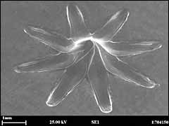
Once a laser beam experiment had been conducted in vacuum it seemed the natural step forward was to repeat the experiment using an electron beam, arranged to produce as closely as possible the processing parameters used with the laser experiment. Figure 5 a) and b) shows SEM images of the results of this comparison. It is clear that there is a very large difference between these two features. Figure 5a) is the result of using a laser power of 1kW, a scan speed of 16m/min with 10 swipes per leg, using a spot size of 0.33mm. Figure 5b) uses an electron beam with identical parameters apart from a spot size of 0.13mm (the largest available). Figure 5c) shows the results of using an optimized set of electron beam parameters for titanium (based on a large amount of pre-existing data) and applying the same programmed path. It can be seen that the shape resulting from use of these new electron beam parameters is also very different from the shape produced by the laser beam in vacuum, but now very closely resembles the actual programmed path. It is clear that much more work needs to be performed using laser induced Surfi-Sculpt in order to bring it to the level of the current performance of electron beams for this process, and it is hoped to report some of this at a later date.
|
Fig.5a) Laser in vacuum
|
Fig.5b) Electron beam - closest approach to parameters used for a)
|
 |
 |
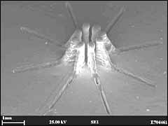 |
Fig.5c) Electron beam - optimised parameters
|
Potential applications
Potential applications of the Surfi-Sculpt power beam process are discussed below. Some of these have already been implemented, using electron beams, on a commercial basis, but at the moment no applications involving laser beams have reached production.
Orthopaedic implants - the surface of such devices can be modified to improve the fixation of metallic implants by encouraging bone in-growth. There are alternative techniques for making these surfaces, but a Surfi-Sculpt process offers the potential benefits of being fast, of allowing close control of the feature shapes and of ensuring surface features are firmly bonded so that they do not detach from the implant. The general social trend for increased life expectancy, and an expectation of patients to be mobile and active in old age, means that the market for orthopaedic implants worldwide is increasing at an annual rate of 7%. In 2005 the total number of hip or knee replacements in US and Europe was 814,000. It is estimated that 10% of these will fail - the overwhelming majority because of aseptic loosening, so the requirement for improvement is immediate and is of significant social benefit.
Composite to metal joining - composite materials are increasingly being deployed into applications where previously metals were the predominant choice of material. Carbon fibre composite materials account for some50% of the mass of Boeing's 787 Dreamliner, for example, and this is a major factor in the claimed 20% improvement in fuel efficiency. Glass fibre composite is being increasingly deployed in ship superstructures and for internal panels- producing a lighter weight structure which improves fuel efficiency, payload and, above the waterline, reduces the tendency to roll. It is frequently a design requirement to join composite to metal. The production of surface features that allow a metal component to bond too many layers of laminate potentially can improve the bond strength. This technique is currently being assessed for a number of different products.
Heat exchangers - thermal management of microprocessors and associated systems has become particularly challenging both at chip level and at the system level in data centres. The density of semiconductor devices has continued to increase, as is evident within desktop computers, where the last few years has seen more elaborate solutions to air cooling, and even the introduction of liquid spray cooled devices. A variety of small features produced with power beams, that provide beneficial fluid flow and improved heat transfer are being investigated.
Ultra-thick coatings - within work that is focused on the manufacture of the plasma facing components of the ITER fusion vessel, the steel substrate has been treated with electron beam Surfi-Sculpt prior to applying an ultra-thick (e.g. 3mm) tungsten layer using vacuum plasma spray. The process has been shown to be beneficial in preventing 'peeling' of the layer, that normally occurs due to the high residual stress built up as a result of the mismatch in expansion coefficient. It is anticipated that this process may have many other applications where it is desirable to apply thick coatings.
Conclusions
The objective of the work reported here was to demonstrate that Surfi-Sculpt like features could be produced using laser beams as well as electron beams. From the results presented, it would appear that similar mechanisms and physical processes are involved in the generation of these features, whether laser beams or electron beams are being used. However, it is clear from the comparison experiments performed that there are some differences, particularly related to the optimised scan speeds, which appear higher when using electron beams. With laser beams, the process lends itself to the use of high brightness fibre delivered laser beams and galvanometer driven scanning systems, although it is possible that some shapes might be produced by using a fixed beam and manipulating the workpiece. The main compromise for the latter will be speed of movement. As well as producing Surfi-Sculpt features in metal, this work has shown that it should also be possible to produce similar features in plastic material, notwithstanding the large difference in viscosity of the molten material. When processing titanium alloy, a significant influence of the atmosphere in the region of the process was noted.
Acknowledgements
This work was funded by the industrial members of TWI, as part of its Core Research Programme. The authors would also like to thank Bruce Dance from TWI's Electron Beam Group, for performing the electron beam comparison experiment and for useful discussions. Colleagues at IPG Photonics, SPI Lasers and Trumpf, should also be thanked for use of their equipment in these trials.
References
- Dance B G I and Kellar E J C 2002: Workpiece Structure Modification International patent publication number WO 2004/028731 A1. Applicant: The Welding Institute.
- Dance B G I 2002 Modulated Surface Modification Int. Patent Publication Number WO 2002/094497 A3 Applicant: The Welding Institute.
- Dance B G I and Buxton A L 2006 Surfi-Sculpt a new electron beam processing technology 8th Int. Conf. on Electron Beam Technologies Varna.
- Dance B G I and Buxton A L 2007 An introduction to Surfi-Sculpt technology - new opportunities, new challenges. Conf. Proc. 7th Int. Conf. On beam technology, Halle 17-19 April 2007.