Background
A very wide range of Friction Stir Welding (FSW) tool probe and shoulder designs have been developed around the world over the last 30 years, many of which have been used successfully and some patented. However, there has never been a standard FSW tool probe shoulder design that has been incorporated into standards and specifications such as BS EN ISO 25239-1:2020 friction stir welding aluminium, or AWS D17.3/D17.3M:2016 specification for friction stir welding of aluminium alloys for aerospace applications. Although there is not a standard FSW tool probe shoulder design, there is now a few companies offering “off the shelf” FSW tools. However, the majority of FSW users consider their FSW tool designs as confidential and, as such, there are very few public domain papers that discuss detailed FSW tool geometries and dimensions or the exact material composition from which they are made.
Since its invention back in 1991, TWI has continuously developed the FSW process for a wide range of applications for our Member companies. This has involved the design of FSW tools, weld parameter development, FSW machinery operating specifications and design, and also prototype FSW machine manufacture. Throughout that period of time it has always been recognised that the FSW tool is a crucial component for the production of high quality welds.
Basic Principles
In order to discuss how a FSW tool is designed, we first must understand its various roles...
To generate a solid state weld between pieces of metal, the FSW tool probe and shoulder combination are rotated and plunged into the interface between two plates/sheets under an applied axial force, which keeps the FSW tool in the correct location during the weld cycle, as shown in Figure 1. It is very important that the plates/sheets are supported in a clamping fixture, on the underside by (usually) a steel backing bar. This bar has the purpose of reacting to the axial force. In addition, side clamping is required to prevent the plates/sheets from separating as the FSW tool is traversed along the weld interface. Rotation of the tool generates frictional heating and softens the weld interface region and when the aluminium alloy is sufficiently softened the tool is traversed along the weld interface.
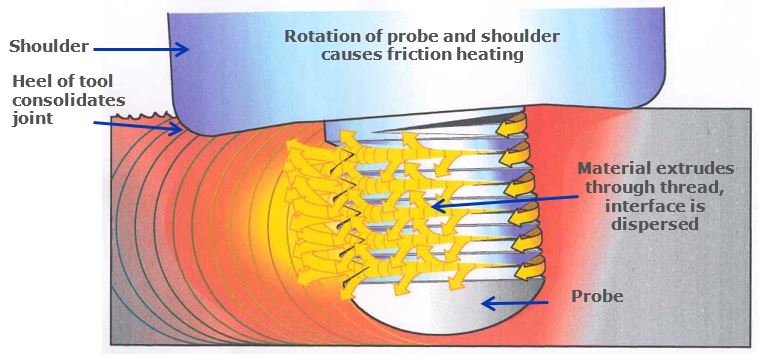
As it rotates and is traversed the thread form on the probe body disrupts the softened weld zone material and also crushes and disperses any oxide film at the joint interfaces. Complex forging and extrusion occurs and softened material is transferred through 180° from the leading edge to the trailing edge of the probe, generating a solid-state weld as a result of time, temperature and pressure. As the rotating shoulder (shown in Figure 1) is traversed along the weld interface it applies a compressive force onto the surface of the plates/sheets, both heating and containing the softened material beneath. The plates/sheets can be joined using lap welding or butt welding approaches.
Early Developments
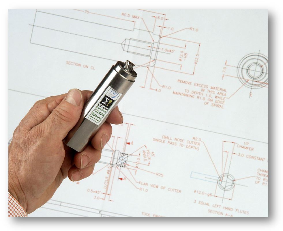
The starting point FSW tool probe design consisted of a simple parallel-sided (cylindrical) threaded probe body, which rapidly became the first industrially successful probe in 1995. Since then, TWI has progressively developed a family of FSW tool probes, as shown in Figures 2a-e, with the original parallel, threaded pin shown in Figure 2a. The thread form was cut onto the probe body in the left hand direction.
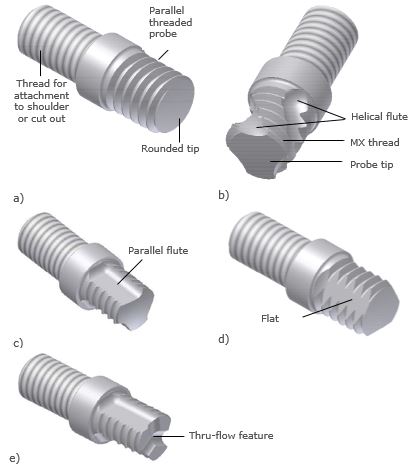
Figure 2 FSW probe designs: a) Threaded pin; b) MX-Triflute™; c) Parallel flute; d) MX-Triflat™; e) Thru-flow tip feature applied to a parallel flute tool.
Tool Design Evolution
As the development of FSW has progressed, commercial users of the process demanded faster welding speeds in much higher strength aluminium alloys and that is the point at which the MX-Triflute™ probe was developed. A version of an MX-Triflute™ probe is shown in Figure 2b which, although not obvious, has a slightly tapered body. The tapered probe body and the three equally spaced helical flutes, identified in Figure 2b, displaced very much less material during the weld cycle than the original cylindrical body probe and thus much faster welding speeds could be achieved, whilst maintaining high quality. The three flutes and the MX thread form also created a more active disruption of weld zone materials and more rapid generation of frictional heating, which improved the FSW process efficiency. MX-Triflute™ FSW tool probes tend to be used for welding thinner <15mm workpieces and the MX-Triflat™ FSW probe >15mm.
FSW tool shoulders are generally less complex in their design than probes. The tool shoulder does not necessarily run parallel to the workpiece surface, in simple linear welds the tool is often tilted such that the trailing edge of the shoulder penetrates the workpiece and applies additional forging pressure. Dawes et al (1995) developed a concave shoulder design which worked reliably at an operating (tool tilt) angle of 2-3˚ (Figure 3a). The desire to increase welding speeds in 5xxx series aluminium alloys led to the development of a scroll shoulder (Figure 3a-b), in which a scroll feature is machined into the face of the shoulder which pulls in material from the outer edge of the shoulder to the root of the probe (Dawes and Thomas, 1999). This idea was developed to promote the vertical flow of material, but initial trials showed that such a design modification also allowed the use of a vertical (zero-tilt) tool. This shoulder design is now widely used for applications requiring 2 and 3-dimensional weld paths.
The tool shoulder profile significantly influences frictional heat generation during FSW. Tool shoulder profiles that restrict material flow, such as the scroll, give the greatest heat input, due to increased surface area. Thus, reduced scroll shoulder diameters may be used. This has proved particularly beneficial as joint designs and weld paths are becoming increasingly complex, since tool design can often be driven by joint geometry constraints.
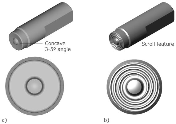
Figure 3 Tool shoulder designs (shown with a plain probe): a) Concave; b) Scroll.
Friction Stir Welding Tool Materials (for Al alloys)
Materials such as intermetallic alloys, silicides, Laves phase alloys (two phase Nb-Ti-Cr alloys), platinum alloys, iridium alloys and ceramics have all been identified as having potential (in terms of high temperature strength) to be used as FSW tool probes for welding aluminium alloys. However, previous research at TWI has shown that most of these materials have very poor fracture toughness and fail rapidly by brittle fracture when used as friction stir tools. In addition, this group of materials are difficult to source, and challenging to machine to the FSW probe geometries currently considered necessary to generate good quality welds.
TWI development over the last 25 years had led to a small group of materials, which can be reasonably easily procured and machined. Previous Al alloy research has included the following probe materials:
- Hot work tool steels (AISI H13 HWTS has been used extensively)
- High speed steels
- Superalloys (Ni- and Co- based)
- Cemented carbides (WC-Co – have limited use)
A comparative summary of these materials is shown in Table 1.
| Tool material | Suitability | Relative machinability | Relative cost | Relative availability |
|---|
| WC |
Good strength, poor toughness at low temperature |
Poor |
Low |
Reasonable |
|
Densimet D176
|
Reasonable strength and toughness |
Good |
Medium |
Good |
| TZM |
Reasonable strength and toughness but produces a hazardous oxide fume at elevated temperatures |
Good |
Medium |
Good |
| Nimonic alloys |
Good strength but relatively low toughness |
Reasonable |
High |
Poor |
| MP159 |
Good strength and toughness |
Reasonable |
High |
Reasonable |
Table 1 Relative properties of various possible FSW tool materials welding high strength Al alloys
For Al alloys, the cobalt-based high strength MP159 alloy has proven itself the best choice available. MP159 was first used at TWI as a FSW probe material in 2001. This alloy was developed by SPS Technologies Inc. to be a fastener alloy capable of operating up to 590°C. At the time of writing, the alloy is manufactured by the Latrobe Speciality Steel Company in the USA. The nominal chemical composition of MP159 alloy is shown in Table 2.
| Element | Co | Ni | Cr | Fe | Mo | Ti | Ni | Al |
|---|
| Wt. % |
35.7 |
25.5 |
19 |
9 |
7 |
3 |
0.6 |
0.2 |
The attractive properties that have led to the use of MP159 for FSW probes are as follows:
- High strength (1445 N/mm2 at 540°C) combined with good ductility and toughness
- High operating temperature (up to 590°C)
- High creep strength up to 590°C
- Can be forged to complex shapes
- Good fatigue resistance
- Can be purchased at a commercially viable price
- Can be machined to complex shapes
Weld Quality and Acceptability
Although often requested, it is often difficult to provide an FSW probe geometry and dimensions for a particular application, because the size of the component to be welded and the heat sink effect of the clamping fixtures required need to be accommodated. Therefore, a particular FSW tool probe type is initially chosen from prior experience, and the design, geometry and dimensions for a starting point probe. A short weld parameter test matrix study is most often carried out to establish if this probe can produce good weld quality, or where the boundary of the weld parameter tolerance envelope is located. In many cases, the original FSW probe design selected produces good quality welds but occasionally a redesign of the tool is required to accommodate any drawbacks that were identified or inconsistencies in the material being welded – e.g. variations in extrusion thickness, edge quality or straightness.
In the absence of any truly reliable modelling information that can accurately identify the exact FSW probe shape for a particular application, alloy type and plate/sheet thickness, TWI find that an empirical and iterative approach still tends to be the best way of developing the FSW technology for our TWI Member companies (see Figure 4). Our approach has so far proved to be successful and has provided confidence for the industrial end user. One aspect which is often over-looked when exploring elaborate ‘optimised’ tool designs with computer modelling is the final ‘manufacturability’ of the tool.
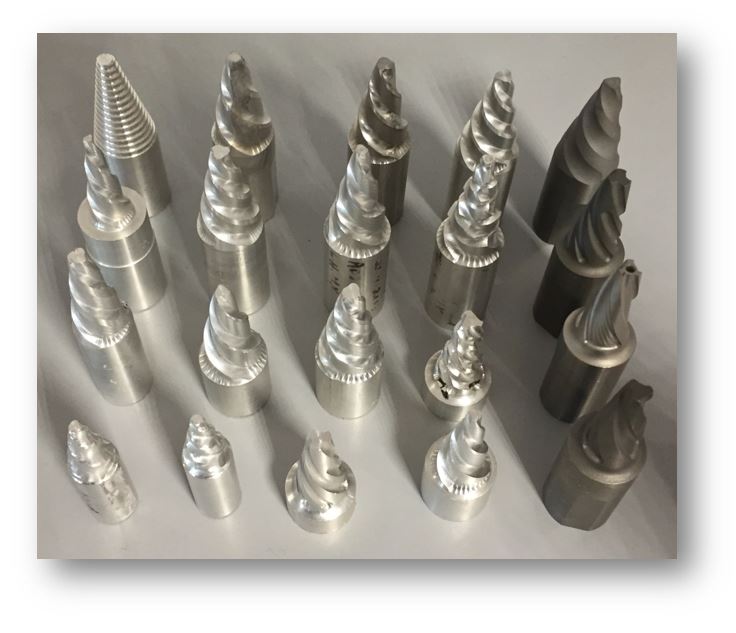
Figure 4 Example of various design iterations explored during a large FSW tool development programme for the welding of thick section Cu-alloy. Machinability is an important factor to consider when designing new FSW tools.
FSW Tools in TWI Research Projects
A FSW Single Client Project at TWI will most often include the delivery an FSW tool design (which then becomes the property of the client), accompanied by tool manufacturing drawings and the most effective and robust production weld parameters, derived from an agreed weld parameter development programme against client KPIs.
Quality is assessed in terms of metallurgical and mechanical joint properties, with the acceptance criteria most often in line with the standard ISO 25239, or dictated by client specification. If a criteria is not available, TWI are able to advise on suitable assessment testing plans to help the Member company establish the tolerable quality and performance acceptance boundaries. This can short circuit an FSW programme that might well have taken a long time to develop successful results in a company with an application but little internal FSW process experience.
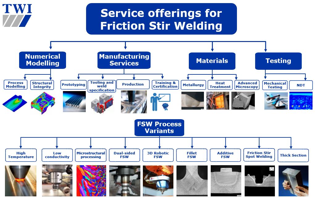
FSW Support Offering at TWI
Since inventing FSW in 1991, TWI has been working hard to maintain our world-leading industrial support and innovation for the technology. Below is a non-exhaustive selection of our FSW technical support offerings and a number of the FSW process variants.
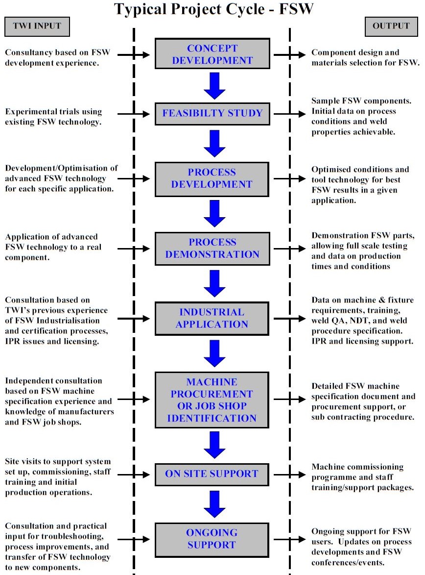
Typical FSW Project Cycle at TWI
Over the years, TWI has devised a risk-managed, staged approach to FSW process development and technology transfer. The diagram below provides an overview of a typical FSW project cycle, which is suggested to be a risk-limiting, confidence-building road map when exploring and adopting the technology.