Tue, 12 October, 2021
TWI asset integrity team has performed conductor analysis services on 48 existing wells for a major offshore oil and gas operator in the Middle East, providing peace of mind that those well conductors are safe to continue service.
Offshore well bores consist of several tubes. The outermost well casing, the conductor, protects the inside casings from aggressive corrosion. The conductor should not leak, nor buckle or collapse under both axial load and bending moment.
Several oil wells are being used beyond their design life. Therefore, ensuring the structural integrity of these wells to prevent unexpected failures has become more important for owners.
The broad scope of work includes a design basis and review of the existing wells to estimate the minimum required thickness (MRT) of offshore well conductor pipes for specific well designs, considering all uncertain parameters.
The wells are categorised into six different groups depending on their functionality (oil producer wells, gas producers, water injectors, etc.). At least, seven wells were introduced in each group and for each well, axial loads and bending moments were reviewed.
Based on this review, the most critical well in each group was selected as the representative well in that group for further analysis.
The strength and stability assessments were performed for the representative well in each group by using finite element software.
The finite element model:
- Includes the conductor, inner casings, surface equipment, jacket lateral supports, and soil support (p‑y soil springs/soil fixity).
- Calculates axial well loads (considering casing eccentricity) in the conductor and casings at the wellhead for each critical drilling stage.
- Perform a strength and stability assessment of the well conductor, connectors, and surface equipment flanges, as required following the IP guidelines and the relevant AISC and API codes, with modifications for the stability of concentric pipes in accordance with Stahl and Baur 1983, and Imm and Stahl 1990.
- Consider environmental loads including a 100-year return period wave.
- Extract bending moments at key surface equipment elevations and along the conductor and then compare against allowable capacities for bending, axial, and lateral/environmental loads (as appropriate).
- Assesses wave and current induced fatigue.
- Checks vortex shedding.
Based on the developed FE model, minimum required thickness (MRT) for each well type was provided. MRT is the thickness below which the required cross-sectional area is not achieved and failure may occur.
 Figure 1. MRT Calculation Flow Chart
Calculation of Probability of Failure
Different parameters contribute to the estimation of the MRT of a conductor well, such as:
- Axial weight
- Bending moment
- Conductor yield stress
- Module of elasticity
- Bucking length
In general, FE Softwares use deterministic values for the above-mentioned parameters to perform the stress analysis and consequently for obtaining the MRT values. However, there are many uncertainties in the applied loads on the conductors (e.g. axial load and bending moment) and in the resistance of the conductors.
Another deliverable of this project was to measure the failure probability of the conductor wells.
Since the exact value of the above parameters is uncertain, instead of a deterministic value, a distribution was assigned to each parameter. Based on the previous studies, log-normal distributions with a COV (Coefficient of Variation) of 0.1 were considered for the above-mentioned parameters. The mean values of the parameters are those values that were used in the FE model.
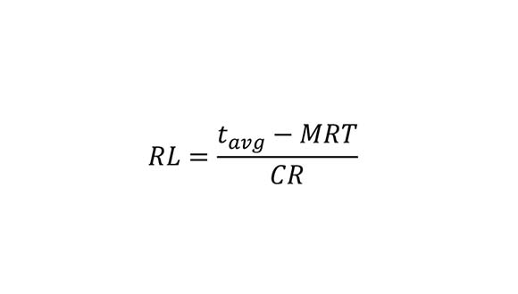
Having assigned distributions for the input parameters, a normal distribution can be assigned to the MRT value. After obtaining the MRT distribution, the remaining life (RL) for the conductors is estimated as:

Where tavg is the averaged measured thickness from the UT results and CR is the corrosion rate for each conductor based on UT thickness measurements.
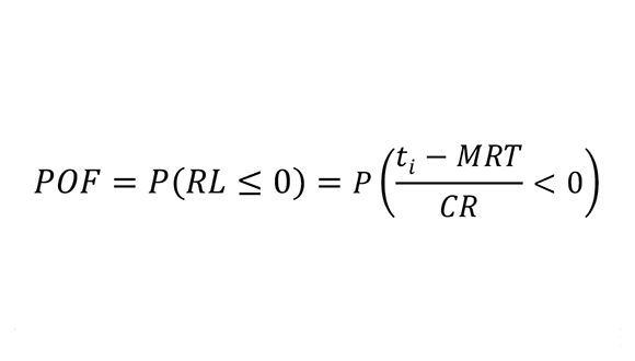
According to the assigned distribution for MRT, a distribution can be assigned to the remaining life. After assigning a distribution to the remaining life, the Probability of Failure (POF) for different conductor thickness (ti) is obtained as the probability of remaining life is less than zero, i.e.:

In each group of conductors, based on the calculated MRT and the estimated CR, the remaining life of the conductor was estimated and some recommendations and mitigation actions were provided. The result of the project is used as a guideline procedure for the further life assessment of conductors as well as the future assessed conductors.
For further information about Integrity Management, and to find out more about TWI’s services to the oil and gas industry, please email engineering@twisea.com
