When carrying out fracture toughness tests on steels or weldments, so-called pop-ins are sometimes observed (Boyle et al [1] , Kamath and Gittos [2] ). Pop-ins appear as discontinuities in the force-displacement traces as exemplified in Fig.1. These are associated with a sudden increase in displacement which may or may not be accompanied by a fall in force. Subsequently, there is an increase in force above the level prior to the pop-in event. Thus, the test specimen has a higher load bearing capacity than implied by the pop-in alone.
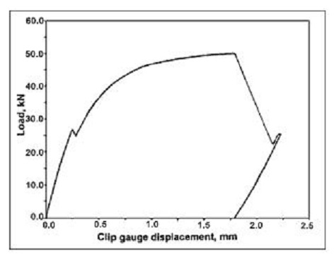
Fig.1. Significant Type I pop-in event in weldment CTOD tests: load-clip gauge displacement plot
Discontinuities on the force-displacement trace which are not followed by higher force levels, relative to that at the discontinuity, are not classed as pop-ins but as failures.
Pop-ins may be due to a number of causes (Dawes et al [3] ) which include the following:
- Initiation and arrest of a brittle crack (i.e. cleavage crack) in local brittle zones present in the material being tested. Usually, these arrested cracks are in the same plane as the fatigue pre-crack, (these have been classified as Type I pop-in by Wiesner and Pisarski [4] ).
- Formation of splits (also referred to as delaminations, separations and fissures) on planes perpendicular to the plane of the fatigue pre-crack (Type II pop-in). [5]
- Linking of multiplane fatigue cracks or joining up of flaws, such as porosity, slag inclusions or lack of fusion with the fatigue pre-crack (Type III pop-in).
- Electrical interference, recorder malfunction or breaking of ice particles formed around rollers during tests at sub zero temperatures (Type IV pop-in).
When pop-ins do occur it is important to establish which of the above caused the event. In general, causes 1 and 2 reflect material behaviour and could be significant with respect to structural integrity. Causes 3 and 4, however, are associated with the test procedure and may require re-tests to be carried out or the event to be discounted.
The treatment of pop-ins occurring in parent material is considered in BS 7448:Part 1 and welds in BS EN ISO 15653. The inhomogeneous nature of welds, coupled with concern in identifying fracture toughness at the initiation of a fracture event means that treatment of pop-ins is more severe in Part 2 than Part 1. Details are given in 11.4 and Annex E of BS EN ISO 15653.
With respect to Type II pop-in, ISO 15653:2010 advises that the pop-in corresponding to split formation may not characterise the fracture toughness of the material for the intended crack orientation (because the split is not in the same plane as the fatigue precrack). A different specimen and crack plane orientation might be necessary to characterise the fracture toughness of the material in the plane of the split.
References
1.Boyle, R W; Sullivan, A M; Krafft, J M: 'Determination of plane strain fracture toughness with sharply notched sheets'. Welding Journal, Vol. 41 (September 1962), p.428.
2.Kamath, M S; Gittos, M E: 'The incidence of pop-ins in fracture toughness testing'. TWI Research Bull., (April 1979), pp.114-122.
3.Dawes, M G; Pisarski, H G; Squirrel, S J: 'Fracture mechanics tests on welded joints'. ASTM STP 995k, pp.191-213, 1989.
4.Wiesner, C S and Pisarski H G: 'The significance of pop-ins during initiation fracture toughness tests'. 3R International Vol. 35 (1996), Heft 10/11, pp.638-643.
5.Pisarski, H G; Hammond, R & Watt, K: 'Significance of splits and pop-ins observed during fracture toughness testing of line pipe steel'. Proceedings of IPC 2008 International Pipeline Conference 29 September - 3 October 2008, Calgary, Alberta, Canada. IPC 2008-64676.