Paper presented at the 5th European Solid Oxide Fuel Cell Forum, Lucerne, Switzerland, 1-5th July 2002.
Abstract
High temperature fuel cells, particularly solid oxide fuel cells (SOFCs) offer the highest achievable efficiencies of all fuel cell systems. However, further developments are required to improve both construction materials and methods of manufacture. The most critical issues are joining and sealing; areas frequently overlooked, but where good knowledge of materials chemistry and best practice is essential. Joining and sealing are widely recognised as key enabling technologies for the successful implementation of SOFCs.
A successful joining or sealing material has to meet several chemical and physical requirements. These include chemical compatibility and matching of coefficient of thermal expansion between components; and stability in strongly oxidising and reducing atmospheres. For example, development of satisfactory seals in planar configurations is of major importance and a variety of glasses and glass-ceramic compositions have been reported. However, at present there is little reliable information regarding long-term performance of these seals, particularly when subjected to repeated temperature cycling.
This paper will review a variety of joining and sealing processes including brazing, glasses and glass-ceramics, thermal spraying and sol-gel technology for application in SOFCs.
Introduction
A SOFC is an energy conversion device composed of solid state components. A planar design provides the simplest configuration where the cell components are configured as thin flat plates or layers (
Fig.1). The main components include porous fuel and air electrodes (anode and cathode) and a dense oxide ion conducting ceramic electrolyte. The interconnect, or bipolar gas separator, connects the anode to the cathode of an adjoining cell and has ribs on both sides which function as gas flow channels.
The cell works by combining fuel gas and oxygen at temperatures in the range of 950-1000°C, creating a direct current voltage of 0.7-0.8V per cell. [1]
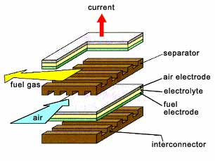
Fig.1. A typical planar design
The planar cell design offers improved power density when compared to the tubular design. [2] This is due to the shorter path length, which minimises ohmic losses. However, a consequence of the planar design is that high temperature gas-tight sealing is a major problem. The components are not continuous, as with the tubular fuel cell; therefore, there are more edges to be sealed. Joining and sealing are required both within the stack, between internal support structures, and externally between auxiliary equipment. However, there are a number of alternative joining and sealing techniques which can be employed to join ceramic to ceramic and ceramic to metal. These techniques must form hermetic joints and seals in both oxidising and reducing atmospheres, at temperatures of 950-1000°C for up to 40,000 hours. This paper will examine brazing, glass-ceramics, thermal spraying and sol-gel technology for use in the fabrication of SOFCs.
Brazing
Brazing is an established technique for the joining of ceramics and metals. It is a liquid phase process and occurs when a braze alloy is melted between two surfaces. On cooling the braze resolidifies and a joint is formed. Brazing materials are commercially available in foil, wire and paste forms. Brazing has the potential to be a joining and sealing process for fuel cells; however, there are a number of issues that must be considered initially, such as specific design of the joint area, materials properties and chemistry. When brazing ceramics, particularly to materials with dissimilar coefficient of thermal expansion (CTE), the design of the joint must be considered. This is because when cooling from the brazing temperature, the braze alloy and metal component will contract more than the ceramic component. This will introduce residual tensile stresses into the joint which can cause cracking at the interface. However, as ceramics perform well in compression, the incorporation of a certain level of stress in the design of the joint can be advantageous. Brazing ceramics can be difficult due to poor wetting of the ceramic surface. Wetting is measured in terms of the contact angle between the braze and substrate during melting. For poor wetting the contact angle (θ) of the braze is greater than 90°, for good wetting the angle is less than 90°.
Fig.2. Definition of contact angle
The main industrial processes for improving wettability are:
- Metallisation: metal coating and metal hydride treatment can be applied to the surface of the ceramic to which the braze will wet
- Active metal brazing: utilises an active material contained within the braze that will induce wetting
In both cases, the actual brazing operation takes place in a controlled atmosphere, such as nitrogen or argon, or a vacuum better than 10
-4 Nm
-2.
Metallisation and brazing
The main metallisation method is the 'moly-manganese' process and it is most suited to the brazing of alumina. This is due to presence of an intergranular 'glassy' phase within the ceramic, which acts as a binding agent. The technique involves depositing thin layers onto the surface to be joined; for example, a powder mixture of glass, molybdenum and manganese is applied to the ceramic. On firing this leaves a manganese rich zone at the surface (to which it wets and bonds) and an outer region rich in molybdenum. The surface is then plated with nickel and the component can be brazed using a Ag-Cu eutectic alloy. Despite the numerous steps required, this process can be automated.
[3] This technique is particularly suited to creating hermetic joints outside of the fuel cell stack but requires careful control at each stage to prevent contamination.
Active metal brazing
In ceramics that do not contain a glass phase, i.e. zirconia, a different approach is required.
[4] For the 'active metal' process to work, an 'active' element is required that will reduce the interfacial energy of the ceramic to allow wetting to take place. Active elements include Ti, Zr, Hf, V and Al; the most common being Ti. Commercially available active metal braze alloys are mainly based on the Ag, Cu or Ag-Cu eutectic systems with added titanium in the range of 1-5wt%. The brazing temperature required of Ag-Cu-Ti systems is in the range of 730-930°C. Active metal brazing is a single step operation and can be undertaken at a range of temperatures, depending on the alloy used (typically 50-100°C above the liquidus of the braze alloy). The upper working temperature of a brazed joint is usually between 60-70% of the braze melting temperature; however, this can vary with joint design and operating conditions.
Many studies have been conducted to understand the wetting characteristics, reaction kinetics and joint behaviour of ceramics joined using this technique. They show that controlling the reaction layer is critical and the thickness of the layer should be approximately 1-2µm. [3] The joint can fail if the reaction layer is too thin due to the possibility of discontinuous bonding. In certain systems, if the reaction layer is too thick, brittle phases may form causing a reduction in the joint strength.
In addition, the components of the braze alloy (and reaction layer) may be susceptible to migration under fuel cell conditions and this may occur as a function of time. This may adversely affect the fuel cell stack components, e.g. the dense ceramic electrolyte, by diffusion along critical paths causing a decrease in efficiency. However, no studies to date have been made to corroborate this hypothesis.
The service temperature limitations of the Ag-Cu-Ti system is ~450°C. Active metal braze alloys capable of extended use at temperatures greater than 650°C are under development. [5] Although some of these alloys have a limited commercial availability, there remains great commercial interest in increasing their range. Ideally, these alloys will retain their strength and ductility at high temperature, as well as having good oxidation resistance. Alloys with such properties include Pt-Cu-Ti, Pd-Ni-Ti and Co-Ti.
Glasses and glass-ceramics
Glass-ceramics are crystalline inorganic materials formed from controlled crystallisation of a parent glass. They are usually based on silicate materials, typically aluminosilicates containing one or more metal oxides. Typical glass-ceramics include celsian (BaO-Al
2O
3-SiO
2), cordierite (MgO-Al
2O
3-SiO
2) and lithium disilicate (LiO
2-Al
2O
3-SiO
2). These materials are easy to process in the glass phase, either in powder form or as a melt. The main advantage of glass-ceramics is the ability to predict thermal, physical and mechanical properties by modifying their microstructure. In general, most systems are suitable for application at temperatures up to 1200°C, however this can be increased with compositional modification. In addition, the CTE can be altered within a range of 0-20 x10
-6/°C allowing it to be matched to a wide range of ceramics and metals.
Glass-ceramics can be used as bonding media, particularly for oxide ceramics containing an intergranular glass phase, which can facilitate wetting. Although, they are brittle in nature, their composition can be modified to provide a wide range of CTEs. As such they can make ideal interlayer materials, which can be employed to reduce the strain gradient of the joint. [6]
A multilayered or graded interlayer design can be employed only when thickness of the overall layer is not an issue. A graded structure is achieved by controlled compositional changes in the chosen glass-ceramic to bridge between the components. If joining to a metal, an oxidation layer on the metal surface is important in order to achieve a successful joint. The reaction between the oxide on the metal surface and the glass-ceramic will facilitate bonding. However, any changes to the composition of the glass-ceramic may not only affect the CTE, thermal and mechanical properties but also degrade the hermetic quality of the bond. Detrimental interfacial reactions between the glass-ceramic and the substrate must be inhibited, and as such surface preparation is critical to create a bond without excessive residual stresses.
Glass-ceramics can also be used as surface sealant materials, [7] although careful control over stoichiometry is required to avoid compositional changes within the working environment of the fuel cell. They can produce gas-tight seals and, when compositions are accurately designed and established for a specific application, they offer a reproducible process. This in turn will significantly reduce costs giving the potential to be competitive with brazing and producing good mechanical properties at elevated temperatures.
Thermal spraying
Most major engineering industry sectors have employed thermal spraying for component coatings for many years. Thermal spraying can be divided into four main categories; high velocity oxyfuel (HVOF), plasma, arc and flame spraying. The fundamental principles of all of these processes are similar. A powder or wire is fed through a spray pistol, heated until molten or soft, and projected at speed onto a substrate to form a coating. The density of the coating is dependent on the material, the state of the particle (solid/liquid ratio) on impact and the particle velocity. The morphology and the particle size range of the initial powder must also be carefully controlled in order to achieve a successful coating.
The bond between a sprayed coating and the substrate is primarily mechanical (not metallurgical or fused). Adhesion of the coating to the substrate depends on all of the above factors plus the condition of the substrate surface, which must be clean and roughened by grit blasting or machining prior to spraying.
The benefits of thermal spraying include:
- Comprehensive choice of coating materials: plastics, metals, alloys, ceramics, cermets and carbides
- Ceramic coatings in the thickness range of 1-2mm can be applied at high deposition rates as shown in Table 1
- Coatings are mechanically bonded to the substrate; therefore, it is possible to spray coating materials which are incompatible with the substrate, e.g. materials with a higher melting point than the substrate
- Components can be sprayed with little or no pre- or post-heat treatment, and component distortion is minimal
- Thermal spray coatings may be applied both manually and automatically.
Table 1 - A comparison of thermal spraying process and coating characteristics
| | Particle Velocity (m.s-1) | Adhesion (MPa) | Oxide content (%) | Porosity (%) | Deposition rate (kg.hr-1) | Typical deposit thickness (mm) |
|---|
| Flame |
40 |
<8 |
10-15 |
10-15 |
1-10 |
0.2-10 |
| Arc |
100 |
10-30 |
10-20 |
5-10 |
6-60 |
0.2-10 |
| Plasma |
200-300 |
20-70 |
1-3 |
5-10 |
1-5 |
0.2-2 |
| HVOF |
600-1000 |
>70 |
1-2 |
1-2 |
1-5 |
0.2-2 |
Thermally sprayed ceramic coatings are an easily automated way to seal specific areas within the fuel cell stack. It has been demonstrated that it is effective for the fabrication of thin gas tight layers for SOFCs. [8] Processes such as HVOF and plasma spraying are attractive due to the fast deposition rate and the ease of masking for deposition of patterned structures. When compared to other film forming processes, such as electrochemical, chemical and physical vapour deposition (EVD, CVD and PVD), thermal spraying can be considered as a means of reducing manufacturing costs.
In addition, thermal spraying has the advantage of manufacturing functionally graded materials within the millimetre thickness range. [9] Compositionally graded coatings in the thickness range of 40-60æm range can be achieved. This may be important when sealing between components of differing CTEs within the SOFC stack.
Sol-gel technology
Sol-gel is a processing technique employed where thin coatings are required with specific physical and functional properties. It can be considered alongside the more expensive deposition routes such as CVD and EVD. This process can deposit coatings on complex geometries at low temperatures (500°C). A precursor and a suitable solvent are mixed to form a solution, which is hydrolysed and condensed to form a gel. The two main types of sol-gel are colloidal and polymeric. Powders and coatings are just two of the applications available for use as a sealant in a SOFCs (
Fig.3).
Fig.3. Sol-gel processing routes (Amorphous particles, nanometer scale, water-based, metal alkoxides or salts, molecular scale, solvent based)
The types of sol-gel are distinguished by the precursor used. The colloidal route utilises fine powder to form multicomponent systems, such as aluminosilicates. The polymeric route employs smaller scale precursors such as alkoxides, which give greater flexibility in the end product than the colloidal route, making it the most commonly used sol-gel route.
Sol-gel can produce uniform crystalline particle size powders, which allows greater morphological control leading to greater homogeneity and purity. Sol-gel derived materials can be fully densified at temperatures 70% lower than conventionally produced powders. This is due to the production of nano-sized powders leading to an inherently high surface area. Sol-gel can be used to fabricate dense structures for use in the SOFC, or be tailored to the substrate material and be used as a surface sealant.
Sol-gel coatings can be modified with additives to provide functional properties such as adhesion, abrasion and corrosion resistance. Application of the sol-gel solution to the substrate is either through spinning, dipping or spraying. Thin films of <1µm can be deposited by dip-coating or spin-coating using small amounts of raw materials. The samples are dried and fired to remove the organics from the coating. The coating subsequently crystallises during the firing cycle to produce a uniform and homogeneous structure.
In order to improve the mechanical properties of the coating, ceramic particles can be dispersed within the sol-gel matrix to form a composite material. This allows fabrication of thick coatings in the range of 5-200µm. Cracking of the coating is limited due to the powder particles acting as crack inhibitors. Volume shrinkage is also reduced (due to a reduction in volume of the matrix) producing a strong bond between the particles, the matrix and the substrate. The final coatings therefore show a decrease in porosity and an increase in density. [10]
In summary, the coating can impart corrosion and abrasion resistance, promote adhesion and densification and increase strength. [11] Sol-gel films applied to porous or abraded surfaces within the SOFC increase the tensile properties of the substrate and act as a sealant. This is due to the action of filling surface flaws and open porosity. Dense, pinhole free layers can be prepared, which are compatible with the substrate and the film chemistry can be precisely tailored.
Conclusions
Joining and sealing are widely recognised as key enabling technologies for the successful implementation of SOFCs. This paper describes alternative techniques for joining and sealing. Brazing, glass-ceramics, thermal spraying and sol-gel may offer solutions to existing problems. The specifications required of these techniques are constantly being improved to meet the demands being placed on the components of the SOFC. These requirements are being met by new materials or by improved fabrication of existing ones. However, it is important that joint configuration, chemical interaction and substrate surface preparation are carefully controlled when applying these techniques. It is the design of the bond and the processing route, which will determine the integrity of the component within the fuel cell environment.
References
-
BCH Steele, Survey of Materials Selection for Ceramic Fuel Cells, British Ceramic Proceedings, UK, 1996
-
SC Singhal, Status of SOFC Technology, Proceedings of the 17 th Risø International Symposium on Materials Science, Denmark, 1996
-
MG Nicholas, Joining of Ceramics, Institute of Ceramics, Chapman and Hall, 1990
-
M Schwartz, Brazing for the Engineering Technologist, Chapman and Hall, 1995
-
D Conquest, KM Knowles, L Ecclestone, JA Fernie, Brazing of alumina for high temperature applications, CIMTEC, Italy, July 2002
-
WB Hanson, JA Fernie, Glass-Ceramics - An Overview, Materials Technology 8 (3/4), 1993
-
C Bagger, N Christiansen, PV Hendriksen, EJ Jensen, SS Larsen, M Mogensen, Techno-economic problems of SOFC commercialisation, Proceedings of the 17 th Risø International Symposium on Materials Science, Denmark, 1996
-
K Okumura, Y Aihara, S Ito, S Kawasaki, Development of thermal spraying-sintering technology for SOFCs, Journal of Thermal Spray Technology, Vol.9 (3), 2000
-
K Barthel, S Rambert, ST Siegmann, Microstructure and polarisation resistance of thermally sprayed composite cathodes for SOFC use, Journal of Thermal Spray Technology, Vol.9 (3), 2000
-
RW Jones, Fundamental principles of sol-gel technology, Institute of Metals, 1989
- D Segal, Chemical Synthesis of advanced ceramic materials, Cambridge University Press, 1989