David Howse
Presented at International Conference on 'Exploiting advances in arc welding technology', Cambridge, UK, 30-31 March 1998
Abstract
Experiments with fluxes for TIG welding which increase the penetrating capability of the process were conducted in order that the mechanism may be better understood. Various theories proposed to account for the increased penetration were discussed and used to determine an experimental programme of work with welds made by the TIG, laser and electron beam processes. It is concluded that the increased penetration is related to arc constriction rather than a change in the thermal coefficient of surface tension (TCST) or any other mechanism. Productivity benefits associated with the increased penetration are noted. It is also proposed that as the mechanism is related to arc constriction rather than TCST the A-TIG process will not be susceptible to problems with inconsistent penetration due to cast to cast variation in stainless steels. Recent developments for the fluxes have concentrated on developing procedures with filler wire giving increased penetration and developing fluxes for other materials such as titanium and nickel alloys.
1. What is the A-TIG process?
Activated fluxes that increased weld pool penetration of TIG welding (A-TIG fluxes) were first utilised in the late 1950s by the EO Paton Institute of Electric Welding in the former Soviet Union. The use of these fluxes reduces both the need for edge preparations and increases productivity due to the reduction in the number of weld passes required to make the joint.
These fluxes have been introduced recently outside of the former Soviet Union and have generated a great deal of interest in how the fluxes produce increased penetration in TIG welds. A number of mechanisms have been proposed to account for the observation that the arc is visibly constricted by a surface coating of flux. The concentrated arc energy may increase weld penetration through an arc or weld pool mechanism.
As yet, the A-TIG flux technology has only been exploited for TIG welding C-Mn and stainless steel grades. The activated flux technology may have much wider applications than these and there is a need to fully understand the mechanisms at work in order to exploit the process and investigate the possibility of applying the flux technology to other welding processes and materials.
|
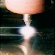
a) without flux
|
b) with flux
|
 |
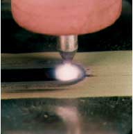 |
| Fig.1 Comparison of the TIG arc showing constriction |
The A-TIG arc shows a visible constriction of the arc compared with the more diffuse conventional TIG arc at the same current level, Fig.1. This more focused arc will increase the penetration depth by between 1.5 to 2.5 times that produced with the conventional TIG process. The typical A-TIG weld bead penetration profile in 6mm thick stainless steel is shown in Fig.2. This can be compared with the weld bead penetration of approximately 3mm for the conventional TIG welding process which was produced on the same thickness of plate and with the same welding parameters in Fig.3.
Fig.2 Conventional TIG weld in 6.0mm thickness austenitic stainless steel
Fig.3 A-TIG weld in 6.0mm thickness austenitic stainless steel
2. Mechanism for increased penetration
A literature review carried out as part of the TWI Core Research Programme revealed that a mechanism had been proposed which was based on the effect on the arc plasma to explain the action of the flux
[1] . However, it was also thought that the increase in penetration could also be due to a change in the thermal coefficient of surface tension (TCST) producing a Marangoni effect in the weld pool.
In order to establish whether the effect of the fluxes was due to constriction of the welding arc, Marangoni flow, some other mechanism or a combination of these, a number of different welding processes were used to make welds with the A-TIG flux AFP SS1. Welding processes evaluated with the flux were:
TIG with Ar shield
TIG with Ar/He shield
Keyhole plasma
CO2 laser
Electron beam
It was intended that within this range of processes any separate effects of the flux coating and the weld pool could be differentiated. The welds were all made on one cast of austenitic stainless steel and macrosections showing weld profiles were produced.
The A-TIG flux produced an effect with the TIG process in both argon and helium shielding and the plasma process. This work showed that the A-TIG fluxes produced different and cumulative effects to the increased penetration associated with 'hotter' gases such as helium and also showed that the flux had some effect on other processes such as plasma. However, it was not clear from these welds whether the effect was due to arc constriction or weld pool flow.
The laser welds carried out in this programme of work were made to investigate the effect of the A-TIG fluxes on the molten pool without the influence of a current carrying welding arc. It can clearly be seen that the A-TIG fluxes do also have an effect on the penetration of the weld in the conduction limited mode (Figs.4 and 5). There is, however, a plasma associated with these CO2 laser welds and it is thought that the wider top portion of the laser weld profile is caused by the heating effect of the plasma rather than the effect of the laser beam itself. It was noted that the plasma visibly constricted when the weld moved into the flux coated region.
Fig.5 CO2 laser weld with A-TIG flux
It was decided to make electron beam melt runs to investigate welding without the usual arc or plasma in order to attempt to separate any effects of arc or plasma constriction and surface tension caused by the flux. The welding parameters were selected to provide a diffuse energy beam, akin to a conventional TIG arc. It can be seen that the electron beam melt runs do not show significant increase in penetration due to the A-TIG fluxes in the same way that welds made with arc, plasma or laser processes do (Figs.6 and 7).
Fig.7 Electron beam weld made with A-TIG flux
Fig.8 Proposed mechanism for the A-TIG process
It was concluded from this work that the most plausible theory at present is that the arc or plasma is constricted by the action of the fluxes. The arc constriction ( Fig.8) increases the current density at the anode root and with the increase in the arc force, a substantial increase in the penetrating depth of the molten pool can be achieved compared with conventional TIG at the same welding current. Although there are a number of effects resulting from the use of activating fluxes, it is thought that the increased penetration associated with the fluxes is not caused by a change in the thermal coefficient of surface tension of the weld pool (Marangoni flow).
3. Practical applications and recent developments
The primary benefit of the A-TIG process is the capacity to weld components in a single pass using a square edge butt preparation. In comparison, when welding material thicknesses above 3mm using the conventional TIG process, it is normal practice to machine the edges of the material i.e. to use a joint preparation. Additional costs are incurred through the machining operation and the substantially greater welding time, as several passes are required to fill the joint.
The A-TIG process is capable of welding up to 12mm in a single pass without filler material; using the conventional TIG process, 6 passes or more would be required. For greater material thickness, it is recommended that a two-pass welding technique is employed, one pass from each side; making it possible to weld material up to 20mm thickness.
Although the flux is capable of penetrating to a depth of approximately 12m thickness, the weld bead will require support while the weld is being made. If this is not done, the weld bead will sag and have an unacceptable profile. Clearly, there is also a limit in terms of the thickness of joint that can be welded in a single pass requiring no backing or support, i.e. supported by the material's own surface tension. This is particularly important for determining whether orbital tube to tube welds can be made in a single pass. Work has been carried out to establish the maximum thickness limit for a number of conditions and these results are shown in Table 1.
Fig.9 Butt weld in 20mm thickness stainless steel with 7mm A-TIG root pass
As can be seen from the above, another possible application of the fluxes is to reduce the amount of filler material required to make a joint in thicker section material.
Figure 9 shows a macrograph of a weld sample in 20mm thickness stainless steel. The TIG root face is 7mm thickness welded in a single pass, thus reducing the amount of subsequent filler material required to make the joint by approximately 30% compared to a conventional TIG root.
As the mechanism for increased penetration appears to be related to arc constriction rather than surface tension effects, the A-TIG process does not appear to be susceptible to material (cast to cast) variations normally encountered in austenitic stainless steels. In austenitic stainless steel, providing the appropriate flux is used, it should be possible to weld a wide range of material casts using the same welding procedure including welding modern 'cleaner' steels containing, for example, low sulphur and high calcium levels.
Table 1. Maximum thickness weldable in a single pass requiring no support
| Joint type | Maximum thickness |
|---|
Orbital tube to tube weld
Stainless steel
Welding position K/5G
Continuous current |
6.0mm |
Orbital tube to tube weld
Stainless steel
Welding position K/5G
Pulsed current |
5.75mm |
Root pass in butt joint
Stainless steel
U preparation
Welding position PA/1G
Continuous current |
7.0mm |
All of the above information has been generated for carbon-manganese and stainless steels and for autogenous welds made with a mechanised welding process. However, it is also possible to use the fluxes to weld manually and procedures have been qualified on plate material up to a maximum thickness of 6.0mm welded in the flat (PA/1G) position. However, manual positional welding of root runs without backing will require a reduction in the maximum thickness weldable to approximately 4.0mm. Manual welding using the A-TIG fluxes will also require some welder training to obtain consistent root penetration.
Similarly, the flux can be used to produce welds with filler wire and still maintain some increase in penetration. For example, a conventional TIG fillet joint in stainless steel was welded using a procedure with filler wire and problems were encountered with poor fusion at the root, possibly as a result of the material having a very low sulphur content ( Fig.10). A similar procedure was developed using the A-TIG flux and filler wire. A macrosection of this weld is shown in Fig.11 and it can be seen that the root fusion is much improved by the application of the flux.
Fig.10 Conventional TIG fillet weld in 316L stainless steel (<0.002% S)
Fig.11 A-TIG fillet weld in 316L stainless steel (<0.002% S)
Fig.12 Penetration bead of A-TIG weld in 6.0mm thickness Inconel 600 alloy.
Work has also been carried out recently to investigate the possibilities of using the A-TIG process for other materials. The first references published by The E O Paton Institute of Electric Welding (PWI) note the effect of increased penetration when welding titanium alloys
[3,4] . TWI has recently carried out work attempting to reproduce the results of this work but with only limited success. It was concluded that although the fluxes are still effective in producing increased penetration in titanium alloys, the effect is not as pronounced as for the fluxes used for stainless and carbon-manganese steels. A collaborative programme was also carried out with PWI to develop a flux suitable for welding Inconel 600. A flux was developed suitable for this material and
Fig.12 shows the penetration bead for a weld made in 6.0mm thickness Inconel 600 in a single pass.
4. Concluding remarks
The A-TIG process is capable of increasing the productivity and quality of conventional TIG welding in a simple and reproducible manner which will have practical industrial use. Work is continuing at TWI to understand the fundamental mechanisms of the A-TIG process as well as developing further practical applications. It is thought that a greater understanding of the fundamental mechanisms of the process will enable fluxes to be designed giving increased penetration and hence increased productivity for a much wider range of material types than those currently available at the present time.
References
| 1 |
Simonik AG: |
'The effect of contraction of the arc discharge upon the introduction of electro-negative elements' Welding Production, 1976, 3, pp 49-51. |
| 2 |
Lucas W, Howse DS: |
'Activating flux - increasing the performance and productivity of the TIG and plasma processes' Welding and Metal Fabrication, 1996, January, pp 11-17. |
| 3 |
Gurevich SM et al: |
'Improving the penetration of titanium alloys when they are welded by argon tungsten process', Automatic welding, 1965, No. 9, pp1-4 |
| 4 |
Gurevich SM et al: |
'Welding titanium with a non-consumable electrode using fluxes' Automatic Welding, 1966, No. 12 pp 13-16 |
Publication information
In: 'Exploiting Advances in Arc Welding Technology', Proceedings, International Conference, Cambridge, UK, 30-31 Mar.1998. Published by Abington Publishing; Abington, Cambridge CB1 6AH, UK 1999. (ISBN 1-85573-416-8).