Development of the Laser/MAG Hybrid Welding Process for Land Pipeline Construction
David Howse (1) , Robert Scudamore (1) , Andrew Woloszyn* (1) , Geoff Booth (1) and Roger Howard (2)
(1) TWI
(2) BP Exploration, Upstream Technology Group, Chertsey Road, Sunbury on Thames, Middlesex, TW16 7LN, United Kingdom
* Now at Land Rover, Solihull, United Kingdom
Paper presented at International Conference on the Application and Evaluation of High-Grade Linepipes in Hostile Environments in Yokahama, Japan, 7-8 November 2002.
Abstract
Hybrid Nd:YAG laser/Metal Active Gas (MAG) arc welding combines the advantages of laser and arc processes. The high speed and deep penetration characteristics of laser welding can be coupled with the robustness and tolerance to fit-up associated with conventional arc welding processes. Work has been performed at TWI to demonstrate the capabilities of the hybrid welding process for pipeline welding applications. The principle objective of the work was to optimise process variables when hybrid welding with approximately 9kW of Nd:YAG laser power, produced by combining the output from three Nd:YAG lasers. A specially designed fixture, mounted on a Kawasaki JS-30 robot, was used to couple the laser and arc processes.
Welds were produced using API 5L X60 linepipe material in the 1G, 3G and 4G positions. The influence and interactions of welding conditions and joint geometry were evaluated by both non-destructive and destructive testing. Using 8.9kW laser power, coupled with 200A MAG current, the hybrid process was capable of achieving weld penetration in the order of 12-14mm. Weld quality was strongly dependent on both welding conditions and joint geometry, but welds were produced which met the requirements of API 1104 in terms of imperfections in the weld. The range of microstructures observed were predominantly ferritic with some acicular ferrite. Hardness levels were maintained below 350HV5 in both the weld metal and HAZ.
Introduction
Background
World demand for natural gas in the immediate future is expected to be satisfied by the exploitation of currently known reserves. Many of these reserves are however situated in remote locations and there is a need for long distance land transmission pipelines to transport this 'stranded gas' to market. High levels of capital expenditure are required for the installation of such pipelines and unless the construction economics can be improved much of the gas may remain 'stranded'.
Substantial work directed towards pipeline cost reduction has been undertaken in the last few years. A wide range of opportunities for cost savings have been targeted including pipeline conceptual studies and terrain evaluation, pipeline design, specification of materials, procurement of materials and services, construction and operation. [1] Clearly, pipeline welding has a bearing on costs and two aspects may be identified as particularly important. Firstly, the speed of welding, since this largely determines the pace and timescale for construction, and secondly, the number of people employed on site as welders, fitters and associated logistics support staff since this element contributes significantly to the total cost of welding.
Process options for welding pipelines
Initially a review project was carried out by TWI for BP to identify potential options for reducing welding costs associated with land lay of pipelines. [2] This work identified improvements to existing arc welding technology and also highlighted the potential of high power Nd:YAG lasers in reducing costs of pipeline fabrication.
Laser welding has now been developed to the stage where it presents opportunities for cost savings, which arise from automation and the associated reductions in labour content, despite the relatively high capital equipment costs. Two types of laser are commonly used for welding. One using a gas (CO2 laser) as the lasing medium and the other using a crystal (Neodymium doped Yttrium Aluminium Garnet; Nd:YAG). The CO2 laser generates light at a wavelength of 10.6µm and the light is transmitted from the laser to the workpiece by mirrors. The Nd:YAG laser uses an excited crystal and generates light at a wavelength of 1.06µm. This wavelength allows the light to be transmitted through a fibre optic cable to the workpiece. The advantage of fibre optic delivery makes Nd:YAG laser welding particularly attractive for pipe girth welds. Recent work at TWI using power levels up to 8.9kW has demonstrated that the concept of high power Nd:YAG laser welding of land pipelines is feasible. [3] These power levels have been achieved by combining the beams from three separate Nd:YAG power sources into a single fibre.
However, it should be noted that other work has been directed towards the development of orbital CO2 laser welding systems for pipe line girth welds. [4,5] These systems are capable of operating with up to 20kW CO2 lasers and have been subject to extensive laboratory trials. One system has in fact been integrated into a lay barge environment and used to install a trial 10"OD x 0.5" wall pipeline offshore. [5] While CO2 laser systems are suited for use in static and limited motion industrial environments 1.5 and 2kW Nd:YAG lasers have been successfully containerised [6,7] and are potentially less sensitive to the rigours of cross country transportation.
In considering the application of Nd:YAG laser welding to the fabrication of steel pipelines, it is important to note that the majority of previous high power laser welding work relating to C-Mn steels has been undertaken for structural and shipbuilding applications employing CO2 lasers. [8,9] The beam quality of CO2 lasers is better than that currently available with high power Nd:YAG lasers, so Nd:YAG lasers produce wider and different shaped welds with different cooling times. This affects the ability to produce tough, fine grained, autogenous fusion zone microstructures and the susceptibility to solidification cracking. Toughness and sound weldments are fundamental to achieving code acceptance for welding pipelines.
Recently work has been carried out to investigate the use of hybrid laser/arc processing (see Fig.1) for improving the performance of laser welding applications. [10] The advantages of this approach may be summarised as:
- Greater tolerance to joint fit up.
- Increased heat input thus giving increased welding travel speeds or penetration.
- Introduction of filler wire to the molten pool during laser/MAG hybrid processing, allows the microstructure of the weld to be modified and controlled. Potentially this provides positive benefits in terms of meeting weld metaltoughness requirements and also in reducing solidification cracking susceptibility.
Fig.1. Hybrid laser-MAG welding
In fact, hybrid welding has been adopted by the ship building industry and CO2 laser/MAG procedures using a 12kW CO2 laser have been qualified that give acceptable hardness, tensile, notch impact and bend properties. [11] These procedures have been adopted to cope with increased productivity requirements and both butt and fillet weld applications were developed. A further advantage associated with the use of laser based hybrid processes in this industry has been the reduction in thermal distortion due to welding.
Earlier work at TWI has also shown that hybrid Nd:YAG laser/MAG welding is more suitable for pipe welding than autogenous laser welding. [12,13] This paper presents some recent results of work carried out at TWI highlighting the benefits of using Nd:YAG lasers, with power at the workpiece of up to 8.9kW, combined with the MAG arc welding process for girth welding of pipeline steels.
Potential of hybrid laser/MAG welding for pipelines
The fabrication sequence for the land lay of large diameter long distance pipelines using the mechanised MAG processes is generally as follows:
- Pipe facing and fit up.
- Root pass - either by internal welding, or, external welding, usually with internal copper backing.
- Fill passes.
- Capping passes.
Using this method of manufacture, the front-end root welding machine is the rate determining process. For increasing pipe diameter, root run productivity may be maintained by increasing the number of welding heads contained within the internal welding equipment. Although developments in arc welding have concentrated upon making the root pass more efficient and reliable, the speed and deposition rates of the fill/cap welding techniques have also been developed to match the productivity of the root run by using dual torches, tandem wires, and currently work is in progress to develop a dual torch tandem wire process. [14,15,16]
The proposed fabrication sequence being investigated in the work presently reported is for the MAG pass fill stations to be replaced by a hybrid Nd:YAG laser/MAG welding station. An example of this type of joint, but made with autogenous 9.0kW Nd:YAG laser, is shown in Fig.2. [12] Two separate laser power sources/hybrid welding heads or a single Nd:YAG laser system, beam switched between hybrid heads positioned on either side of the pipe, may potentially be used to produce this weld.
Fig.2. Section through pipe wall, showing internal MAG root run, 9.0kW autogenous laser fill and MAG capping pass (mm scale shown)
Experimental programme
Materials
The material selected for evaluation was a typical, commercially available pipeline steel manufactured to API 5L X60. The outside diameter of the pipe was 762mm and the wall thickness was 15.9mm. The steel composition is given in Table 1.
Table 1 Parent steel composition
| Grade | Dimensions
(mm) | C | S | P | Si | Mn | Ni | Cr | Mo | V | Cu | Nb |
|---|
| API 5L X60 |
OD762
wt15.9 |
0.11 |
0.004 |
0.021 |
0.33 |
1.42 |
0.023 |
0.018 |
0.003 |
0.002 |
0.023 |
0.040 |
| Grade | Dimensions
(mm) | Ti | Al | B | Sn | Co | As | Ca | O | N | CE | PCM |
|---|
| API 5L X60 |
OD762
wt15.9 |
0.003 |
0.045 |
0.0003 |
<0.004 |
<0.004 |
0.003 |
0.0001 |
0.0008 |
0.0032 |
0.35 |
0.196 |
Equipment
The laser apparatus used comprised of:
- Two 3kW Haas HL3006D Nd:YAG lasers.
- One 4kW Haas HL4006D Nd:YAG laser.
- A 3-in-1 Beam Combining Unit (BCU) manufactured by HIGHYAG Lasertechnologie.
- A 3mW diode laser used to align the processing head with the workpiece. This was fed through the output head in the same way as the high power Nd:YAG laser output.
- Output housing containing recollimating and focusing lenses.
- An optional co-axial gas shield attached below the output housing.
The output from the lasers was transmitted into the BCU using a step index fibre optic of core diameter 0.6mm and length 30m. A single fibre optic of core diameter 1mm and length 15m transmitted the combined laser power from the BCU to the laser output housing.
A Lincoln Electric Powerwave 455 MAG power source was used. A synergic pulsed welding programme appropriate for 1mm diameter wire and Ar-CO2 shielding gas mixtures was selected for the welding trials.
A purpose built fixture was used to hold both the laser focusing head and MAG torch. The fixture permitted accurate and repeatable control of the relative position and orientation of the two heat sources. Figure 3 shows the laser output head and MAG torch attached to the hybrid fixture, with the laser co-axial gas shield and MAG shroud removed.
Fig.3. Laboratory demonstration of hybrid Nd:YAG laser/MAG welding for pipelines
The hybrid fixture was mounted on a Kawasaki Heavy Industries JS-30 arc-welding robot. The robot controller was linked to both the laser and MAG equipment, allowing independent control of the start/stop for each process during the production of test welds. Welds were made by traversing the output housing across a stationary workpiece.
Procedure development
Preliminary trials using hybrid laser arc welding with 8.9kW laser power
Autogenous bead-on-plate runs were produced using the maximum laser power available; 8.9kW at the workpiece. Welds were made at a range of travel speeds and focal positions on the X60 linepipe material. The aim was to establish baseline parameters which, when used in combination with the MAG process, would allow the hybrid process to achieve weld penetration of 10mm at a minimum speed of 1m/min.
A 1.0 mm diameter solid wire (AWS 5.28 ER70S-G) was used for this work.
The resulting welds were radiographically inspected and sectioned to determine the weld penetration and quality for each condition.
Following this, hybrid welds were carried out using a factorial experiment designed with the aim of assessing the influence and interactions of the most significant variables at this laser power. A full factorial experiment required 18 sets of process conditions (including two mid points) to examine the following four variables:
- MAG current.
- Arc-laser separation distance.
- Lead process.
- Travel speed.
The welds were produced in the 1G position, parallel to the longitudinal axis of the X60 linepipe material cut into 400 x 200mm sections. The other procedure variables, which remained fixed during the trials, were as follows:
- Laser focus position.
- Co-axial gas shielding for the laser.
- MAG torch position at a 55° travel angle (pushing for laser lead, pulling for MAG lead).
- MAG gas shielding flow rate.
- Electrode extension.
Further welding trials examined the influence of joint preparation and welding position on weld quality. Four groove preparations were used as shown in Fig.4(a)-(d). Each was machined along the length of the 400 x 200mm, X60 steel specimens parallel to the longitudinal axis of the pipe. Welds were performed in both the 1G and 3G-vertical-down positions at 8.9kW laser power, and 220-250A, 23-27V MAG conditions.
Fig.4. Joint preparations: a-d) API 5L X60 material
Optimisation of hybrid laser arc procedure
The preliminary trials had highlighted problems with solidification cracking. In an attempt to reduce these imperfections above 8mm penetration, a number of process changes from those listed previously were individually implemented:
- Use of a metal cored filler wire - 1mm diameter (AWS A5.18-93: ER70L-6M). Other potential benefits were identified with the use of a metal core wire such as increased MAG stability and increased penetration.
- Change of process angle, from 17.5° MAG torch to vertical/17.5° laser incidence to vertical, to 5°/30°.
- Process separation distance increase (0-2mm).
- Preparation.
The responses used to evaluate the effectiveness of these approaches were measurement of the solidification defects and porosity, using radiography. The penetration was also measured through sectioning.
Welds were also selected for Charpy impact testing, hardness testing and microstructural evaluation.
Results and discussion
Preliminary trials using hybrid laser arc welding with 8.9kW laser power
Macro-examination of the sections taken from the initial autogenous welds showed the weld penetration in the 7.5-9.0mm range, with the highest levels at the lower, 0.9m/min, travel speed for each focus position. The highest penetration of 9mm was at 0.9m/min with the laser focused 2mm below the surface of the material. Whilst there was minimal porosity in the welds (<0.5% projected area), each weld contained solidification defects.
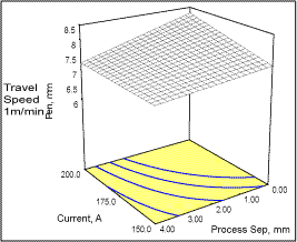
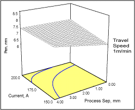
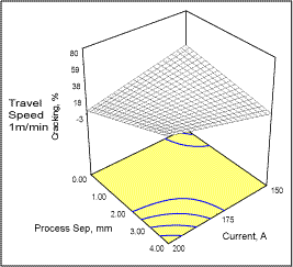
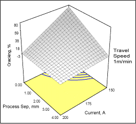
For the factorial experiment carried out using the hybrid process, Fig.5 and 6 show the influence of the process parameters on weld penetration.
 |
 |
| Fig.5. Influence of welding parameters on weld penetration MAG process leading |
 |
 |
| Fig.6. Influence of welding parameters on weld penetration - Laser process leading |
Figure 5 shows results from welds produced with the MAG process leading, at 1m/min and 1.2m/min travel speed. Weld penetration is shown as a function of welding current and laser-arc separation distance. A maximum penetration of 8.5mm was produced at the lower travel speed, with the higher current of ~200A and minimum separation distance of 0mm. Comparing the two plots, the relative influence of welding current and process separation is much more significant at the lower travel speed. At 1.2m/min, there was little difference between the penetration at each current/process separation combination. The minimum penetration occurred at the lower current and at the minimum separation distance.
Figure 6 shows similar plot layouts, but for the laser process leading. As with the MAG process leading plots, penetration was deeper at the lower travel speed and with minimum process separation, resulting in a penetration of 7.8mm. The highest penetration occurred at the lower welding current. However, the overall difference between the penetration at each condition is small; between 7-8mm for each parameter combination. At 1.2m/min travel speed, the highest penetration again occurs at zero process separation, at the lower welding current.
It was noted that significant levels of solidification defects were observed for many of the parameter combinations in this phase of the work (see Fig.7). For the MAG process leading, the welds contained up to 86% defects by summed length. The largest number of these tended to correspond with points on the plots, which had the highest weld penetration. With the laser leading, the welds again showed varying degrees of solidification defects although several of the welds contained no defects. However, these corresponded to lower power welds with 6 to 7.5mm penetration. At 1m/min travel speed, the lowest levels of solidification defects were observed at high current/low process separation and low current/large process separation. At 1.2m/min travel speed, no solidification defects were observed at the higher current conditions.
 |
 |
| Fig.7. Solidification defects as a function of welding parameters for hybrid welds - Laser process leading |
The results of the bead-on-plate factorial suggested the following parameter combination gave the best overall performance in terms of penetration, porosity and solidification defects:
- 0mm process separation.
- 200-220A MAG current.
- 1m/min travel speed.
There was a trade off between which process was ideal to lead during welding (technically neither lead if the laser/arc heat sources are co-incident). With MAG leading, the greatest weld penetration was achieved with minimal weld porosity. However, higher levels of solidification defects offset this advantage. With laser leading, the results suggest that solidification defects can be avoided, albeit with a slight loss in weld penetration.
The weld preparation was modified further, by increasing the depth of the groove to full thickness. In addition, the angle of the welding head was modified so that both the laser and the MAG process was adjusted to 17° each and a more triangular weld bead with 9.0mm penetration and no defects was produced.
Optimisation of hybrid laser arc procedure
The metal cored wire increased the arc stability, which resulted in a smoother top bead. Higher weld penetration was also noted with the metal cored wire. The metal cored wire produced a weld with a penetration of 9mm at 7kW of power at the workpiece in the 1G position (see Tables 2 and 3). Figure 8 is a macrograph of a weld showing 10mm penetration in the 3G vertical up position. The metal cored filler wire did not however, have any effect on solidification cracking above 8mm partial penetration with welds still containing around 70% solidification defects respectively (see Table 2).
Fig.8. Macrograph of hybrid weld showing 10mm penetration using a metal cored wire and 7kW of laser power showing a centreline solidification imperfection
Table 2 Experimental test matrix for phase IV. All welds were carried out with a 150mm focal length, a 1mm laser spot size focused 2mm below the surface of the parent material and at 1m/min.
| Weld ID | Filler Wire | Joint Prep Angle
(degrees) | Position and Direction | Laser Power
(kW) | MAG Power
(kW) | Separation Distance
(mm) | Laser/MAG Angle
(degrees) | Solidification Defects
(% of length) | Porosity
(% of projected area) | Penetration
(mm) |
|---|
| 223 |
ESAB |
25 |
IG |
6.5 to 8 |
4.97 |
0 |
17.5/17.5 |
62 |
0.55 |
9.1 |
| 224 |
ESAB |
25 |
3G v up |
6.5 to 8 |
4.85 |
0 |
17.5/17.5 |
73 |
0.38 |
10.0 |
| 226 |
ESAB |
40 |
3G v up |
8 |
4.66 |
0 |
17.5/17.5 to 5/30 |
0 |
0.29 |
13.2 |
| 230 |
Unifil |
30 |
IG |
8 |
5.6? |
0 |
17.5/17.5 |
17 |
2.13 |
10.2 |
| 241 |
ESAB |
25 |
IG |
8 |
4.83 |
0 |
17.5/17.5 |
|
0.21 |
13.0 |
Table 3 MAG parameters relating to the welds described in Table 2
| Weld ID | MAG Current (A) | Filler Wire | MAG Voltage
(kV) | MAG Power
(kW) | Wire Feed Speed
(m/min) |
|---|
| 223 |
216 |
ESAB |
23 |
5.0 |
10.0 |
| 224 |
211 |
ESAB |
23 |
4.9 |
10.0 |
| 226 |
212 |
ESAB |
22 |
4.7 |
10.0 |
| 230 |
200 |
Unifil |
28 |
5.6 |
15.7 |
| 241 |
210 |
ESAB |
23 |
4.8 |
10.0 |
The welding conditions used for the weld shown in
Fig.9 (see
Tables 2 and 3) resulted in full penetration and the weld was clear of solidification defects. It was evident that if full penetration is achieved, defect free welds above 8mm penetration are possible.
Fig.9. Macrograph of a hybrid weld showing an acceptable weld with 11mm full penetration
The joint preparations investigated in this section of the study are shown in Fig.10. The main consequence of using different preparations is the performance of the process when welding vertically up. Larger angle preparations, such as the 40° angle used in weld W226, produced a larger weld surface width. This resulted in the surface tension being unable to support the weight of the molten pool and hence the weld top bead assumed a highly irregular shape. With a smaller angle, such as the 25° angle used in weld W224, the molten pool is able to support its own weight resulting in a smooth surface bead.
Fig.10. V groove joint preparations used
The changing of weld process angle produced welds with wider top surface beads than those produced with 17.5°/17.5° MAG torch/laser beam incidence angles. Figure 11 is a macrograph of a weld which was carried out using an angle of 10°/25° MAG/laser angle. Figure 11 shows that the width at surface was 7.5mm wide. Figure 12 shows the more typical weld shape encountered in this study having a significantly narrower toward the weld surface and hence a narrower top surface bead (in the case of Fig.12 the surface width was 3.6mm). The weld in Fig.11 exhibited a wide top surface bead but narrow root. The welds carried out with smaller laser incidence angle are narrower and have more of the characteristics of an autogenous laser weld than a MAG weld.
Fig.11. Macrograph of a hybrid weld showing a wide top surface achieved with 10°/25° MAG/laser incidence angles
Fig.12. Hybrid weld, API 5L X60 steel, welded using v-preparation with 1mm and at 1m/min, 8.9kW laser power in 1G (flat) position. mm scale
Table 4 presents the effect of process separation on the penetration, porosity and defect content. It is evident that an increase in process separation reduces solidification defects but to the detriment of penetration. Porosity was not increased significantly due to increased process separation.
Table 4 The effect of increased process separation on penetration, defects and porosity
Separation distance
(mm) | Penetration
(mm) | Solidification defects
(% weld length) | Porosity
(% projected area) |
|---|
| 0 |
12 |
90 |
0.5 |
| 1 |
9 |
18 |
1.3 |
| 2 |
7 |
0 |
0.9 |
Table 5 presents the Vickers hardness values from the weld metal and the heat affected zone of weld W241. The weld metal peak and average hardness are well below the 275HV for weld metal and 350HV for the heat affected zone (HAZ), stipulated in relevant standard BS4515:2000-1 'Welding of steel pipeline on land and offshore'. The HAZ also yielded similar values.
| Weld Metal Hardness (HV10) | Heat Affected Zone Hardness (HV10) |
|---|
| Average | Peak | Average | Peak |
|---|
| 245 |
249 |
240 |
270 |
The results from the Charpy tests carried out on weld W241 are presented in Table 6. The tests were carried out using a standard 10 x 10mm coupon with a 2mm V notch and were tested at a temperature of at -10°C. The results from the weld metal centreline are acceptable, at an average of 109J, being considerably over the 40J minimum requirement. [17]
Table 6 Charpy impact results for hybrid Nd:YAG laser/MAG weld W241 at -10°C
| Position | Charpy Impact Energy (J) |
|---|
| Results | Average |
|---|
| Weld metal centreline |
106 |
130 |
91 |
109 |
| Heat affected zone |
43 |
140 |
90 |
91 |
The average Charpy Impact energy for the HAZ was also acceptable at 91J.The minimum value was lower than for the weld metal, but still acceptable at 43J. Inspection of the fracture surface indicated that there was an increase in brittle fracture area in the 43J specimen compared with the other fracture faces.
Discussion
The 8.9kW laser power bead-on-plate factorial experiment highlighted a number of significant factors that can influence weld penetration and flaw levels. Firstly, the application of the hybrid process does not always guarantee an increase in weld penetration for bead-on-plate welds. Autogenous laser welds in the 1.0-1.2m/min speed range attained 7.5-8.8mm penetration with 8.9kW laser power. For the same speed range, the hybrid weld penetration depth ranged between 6.0-9.1mm. This suggests that at higher laser powers, the hybrid process can give both increased and decreased levels of weld penetration compared to the autogenous laser welding process, depending on the parameter/preparation combination applied.
Considering the problem of solidification defects, the results from the factorial experiment suggested that certain combinations of parameters (laser leading, and higher welding currents) produced sound welds. However, this was a consequence of their reduced level of penetration. The bead-in-groove trials confirmed that higher levels of penetration and/or depth to width ratios would increase susceptibility to solidification defect formation. As such, welding conditions, which maximised penetration, also gave the highest levels of solidification defect formation in the factorial experiment. Whilst the majority of welds below 7.5mm penetration depth showed no solidification defects, if the depth-to-width ratio is high enough, the defect may still occur in welds with penetration depths below this.
Examination of some weld sections, showed that the defect tip was not as sharp as one would normally expect. Also, the solidification pattern around the flaw suggested that it was actually a shrinkage cavity, resulting from inadequate feed of molten metal from the upper part of the weld. A lower depth-to-width ratio triangular weld bead shape that would help avoid crack type defects, would also prevent this type of defect from occurring.
Microstructure and hardness data of these welds showed that desirable ferritic microstructures with acceptable weld metal hardness ranges were obtained. The proportion of the various phases and their distribution throughout the welds were linked to welding conditions (heat input), but more closely to the weld preparation. This was shown by the distinct difference in microstructure in welds where etching bands associated with different microstructure appear to follow the original weld preparation. The relatively small range of welding current/travel speed, and resulting heat input, show weld preparation to be a significant variable in these welds. In addition to offering a method of increasing the depth of penetration, the joint design, in combination with control of welding parameters, also allows control of weld solidification, and the resulting bead profile.
Summary
In summary, the work has shown that it is possible to use high power Nd:YAG laser welding combined with the MAG process to produce deep penetration welding passes in commercially available pipeline steels that meet the requirements of pipeline specifications such as BS 4515 and API 1104 in terms of acceptance criteria for imperfection limits. [17,18] The welds also show acceptable hardness values and good low temperature toughness.
Although the economics of the process need to be further investigated against other competing arc technologies, it is considered that hybrid Nd:YAG laser/MAG welding potentially offers a viable solution for reducing the costs associated with the welding of large diameter steel cross country pipelines.
Conclusions
Conclusions from this work are as follows:
- Using 8.9kW laser power, the hybrid process is capable of achieving a fully penetrating imperfection free weld with 12-14mm penetration depth at 1.0m/min travel speed.
- Using 8kW laser power, and 1.0m/min travel speed, welds can be produced with 8mm partial penetration and no solidification imperfections.
- Weld quality was strongly dependent on welding conditions and joint preparation, but was optimised by adopting procedures which give reduced depth to width ratio welds with the desired weld bead profile.
- The range of microstructures observed varied with both the conditions used and the joint preparation, but were predominantly ferritic with some acicular ferrite.
- Hardness and impact toughness requirements of BS4515-1:2000 can be met using hybrid Nd:YAG laser/MAG processing.
- The use of a metal cored filler wire showed increased MAG stability and weld penetration.
Continuing developments
It appears that procedures are possible which give acceptable quality welds at 8.0mm partial penetration and 12mm fully penetrating. The next phase of work ongoing at TWI is for girth weld procedures to be qualified to international pipeline welding standards using the Nd:YAG laser/MAG hybrid process.
References
- R Espiner 'BP's Pipeline Cost Reduction Project', Proc. Conf. 'New Developments in Land Pipeline', Pipeline Industries Guild, December 2001.
- Booth G S and Hammond J: 'Low cost welding techniques for pipelines'. Proc.Conf. 'Onshore Pipeline Cost Reduction', 'Pipes & Pipelines International, UK and Clarion Technical Conferences, US',Amsterdam, April 2000, Paper 11.
- Olivier CA, Hilton PA, Russell, JD: 'Materials processing with a 10kW Nd:YAG laser facility', Proc. Conf., ICALEO '99, San Diego, CA, 15-18 Nov.1999., Part 2. Section D. pp.233-241.
- Bonigon C and Geertsen C: 'Orbital Laser Welding: A major advance in offshore pipelaying', Proc. Conf. 'Deep Offshore Technology', New Orleans, USA, 1998.
- Gainand Y, Mas JP, Jansen JP, Coiffier JC, Dupont JC and Vauthier C: 'Laser orbital welding applied to offshore pipeline construction'. Proc. Conf. 'Pipeline Technology, 3rd International Conference',Belgium, May 2000, Vol 2. pp. 327-342.
- 'Commercialisation of the transportable oversize waste reduction system (towrs)' www.nuclearmarket.com/proc/D.cfm?ID=1578, May, 2002.
- Ishide T. et al: 'High power YAG laser welded sleeving technology for steam generator tubes in nuclear power plants', Proc. Conf. 'LAMP '92. Laser Advanced Materials Processing - Science and Applications', Niigata, Japan, 7-12 June1992, pp.957-962.
- Kristensen, J.K., Hansen, L.E., Neilsen, S.E. and Borggreen, K., 'Laser Welding of C-Mn Steels and Duplex Stainless Steels', Proc. Conf. 'Assessment of Power Beam Welds', Geesthacht, Germany, 4-5 Feb. 1999,Paper 3.
- Sumpter, J.D.G., 'Fracture toughness of laser welds in ship steel', Advance Performance Materials, 3 (3-4) Jul.-Oct. 1996, pp. 393-405.
- Dilthey, U. and Wieschemann, A., 'Prospects by Combining and coupling Laser Beam and Arc Welding Processes', IIW Doc XII-1565-99, 1999, pp. 29-43.
- Roland, FR et al: 'Laser welding in shipbuilding - an overview of the activities at Meyer Werft', Proc. Conf. IIW, 'Advanced Processes and Technologies in Welding and Allied Processes', Copenhagen, May2002.
- Booth GS et al: 'Hybrid Nd:YAG Laser/Gas Metal Arc Welding for New Land Pipelines', Proc. Conf. 'International Conference on Pipeline Technology', Wollongong, March 2002.
- 'YAGPIPE - Proposal for a Joint Industry Project on laser pipeline welding', TWI Proposal PR4258/EWI proposal 43531CPQ-5, June 2000.
- Blackman SA, Dorling, DV: 'Advanced welding processes for transmission pipelines' Proc. Conf. Pipeline Technology, 3 rd International Conference, Brugge, Belgium, 21-24 May 2000.
- Blackman SA, Dorling, DV: 'Technology advancements push pipeline welding productivity', Welding Journal, 8. Aug.2000. pp. 39-44.
- Blackman SA, Dorling, DV, Howard R: 'High speed tandem GMAW for pipeline welding', Proc. Conf. 'International Pipeline Conference 2002', Calgary, 29 Sep-3 Oct, 2002.
- BS 4515-1: 2000 'Specification for Welding of steel pipelines on land and offshore - Part 1 Carbon and carbon manganese steel pipelines'.
- API 1104: Welding Pipelines and Related Facilities.