Development of Nd:Yag Laser-MAG Hybrid Welding of T Joints for Shipbuilding
C H J Gerritsen 1 , J Weldingh 2,3 , J Klæstrup Kristensen 2
1 TWI Ltd, Granta Park, Great Abington, Cambridge CB1 6AL, UK;
2 Force Technology, Park Allé 345, 2605 Brøndby, Denmark;
3 Currently with Struers A/S, Pederstrupvej 84, 2750 Ballerup, Denmark;
Paper presented at NoLAMP 10 (10th Nordic Laser Materials Processing Conference) 17-19 August 2005 Lulea, Sweden
Abstract
During the 1990s, laser and laser-arc hybrid welding were introduced in production at some shipyards to increase productivity and reduce distortion. To date, these welding systems are based on CO2 lasers and the laser beam is guided using reflective mirrors on Cartesian gantry systems. Although this set-up is appropriate for long, straight welds like those typically welded on panel lines, flexible,fibre-delivered laser power would be more suitable for complex assemblies such as the inside of 'egg-boxes' or for 3D sub-assemblies.
The EU-sponsored project ShipYAG set out to evaluate the suitability of fibre-delivered Nd:YAG lasers for use in shipbuilding. This was achieved by developing a robotic welding cell (including seam tracking, process monitoring,etc.) and welding procedures for two shipyard applications: welding of longitudinal stiffeners and welding of complex subassemblies. This paper describes the Nd:YAG laser-MAG hybrid welding procedure development work from this project incorporating destructive mechanical properties and quality assessment (macrosection, micro-structural evaluation, hardness, tensile, impact toughness and fatigue testing).
1. Introduction
As laser-based welding processes allow narrow, deep penetration welds to be made, the heat input can be greatly reduced in comparison to other processes such as arc welding. This can also reduce the thermal distortion and thereby improve downstream manufacturing productivity. In the shipbuilding industry, where rework to remedy unacceptable inaccuracies and distortion has been estimated to cost up to 15-30% of the labour costs of hull manufacture for new builds [1-4] , employing a low heat input welding technique comes with obvious advantages. As a result, since the 1990s, laser and laser-arc hybrid welding have been introduced in some shipyards. In Europe, where the use of lasers for welding in shipbuilding is most advanced, lasers are now used for production welding on several panel lines.
At the moment, all of the panel line systems use CO2 lasers, as historically these were the only lasers available at powers above 4kW with industrially proven reliability. However, a drawback of CO2 lasers is that the beams (at a wavelength of 10.6µm) can only be guided economically using reflective mirrors. This makes directing and guiding of the beam complex and, as a result, most installations use Cartesian gantry systems. Although this set-up is appropriate for long, straight welds as typically welded on panel lines, flexible, fibre-delivered laser power would be more suitable for complex assemblies such as the inside of 'egg-boxes' or for 3D sub-assemblies.
The beam from an Nd:YAG laser, at the shorter wavelength of 1.064µm, can be guided using flexible, optical fibres. This allows the beam to be easily transmitted to the workpiece by a processing head mounted on a robot and gives simple manipulation of the welding head around complex geometries. The EU-sponsored project ShipYAG [5] set out to evaluate the suitability of fibre-delivered Nd:YAG lasers for welding in shipbuilding by developing a robotic welding cell (including seam tracking, process monitoring, etc.) and welding procedures for two typical shipyard applications: longitudinal stiffeners and complex subassemblies ('egg-boxes'). This paper describes the Nd:YAG laser-MAG hybrid welding procedure development work from this project incorporating destructive mechanical properties and quality assessment.
2. Experimental work
2.1 Shipbuilders' specifications
The work within this project was for specific shipbuilding components (T joints in all cases). At the outset, boundary conditions were specified, based on economic justification, the equipment available, the need for classification society approval and the requirements for shipyard implementation. The main boundary conditions specified were:
|
|
as supplied by shipbuilders (see section 2.2). |
|
|
1.5m/min minimum. |
|
|
4kW maximum at workpiece. |
|
|
3.5mm minimum. |
|
|
up to 0.5mm. |
As reduction of distortion is generally one of the main reasons for moving to laser or laser-arc hybrid welding, the throat size was re-defined specifically for the project. Unlike traditional arc welding, where generally only the external fillet size is considered, the fused laser penetration was included in the calculation of the effective dimensions of the weld, allowing the fillet size to be reduced. Fig.1 illustrates the definition of throat size used. It was measured as the shortest distance from the deepest point of fusion between the two plates to the straight line connecting the weld toes of the fillet (or the tangent of the weld face in the case of a concave fillet). A disadvantage of including the fused laser penetration in the effective weld dimensions of the T joints was that the throat size could only be determined by destructive transverse cross-section sampling, since partial penetration welds were made.
Fig.1. Illustration of the definition used for the throat size (arrow)
2.2 Materials
The following materials combinations were used in this project:
- T joints made from AL24 C-Mn shipbuilding grade steel plates (comparable to S235) in 10mm or 12mm thickness, both for the base plates and stiffeners.
- T joints made from 4mm thickness Holland profile stiffeners ('bulb bars') of AH355 (ERS, equivalent to AH36) grade C-Mn steel to 5mm thickness AH355 (ERS) C-Mn steel base plates.
All base plates and stiffeners were primer coated, but, prior to welding, the base plates were shotblasted in the weld region to remove the primer. The underside of the bulb bars also had the primer removed by grinding or linishing,so there was no primer left on either of the abutting surfaces.
The filler wire used in the MAG process was copper-coated, solid ESAB OK Autrod 12.51 filler wire, of 1.0mm in diameter (wire class EN440-G3Si1 (formerly SG2)). For shielding, initially BOC Argoshield Universal (mixture of 86% Ar -12% CO2 - 2% O2 ) was used. However, this was soon replaced with BOC Weldap 20 (80% Ar - 20% CO2 ) as this gas mixture was preferred by the shipyards where it is already in common use for MAG welding.
2.3 Equipment
The laser source used in these experiments was a Trumpf HL 4006 D solid state, lamp-pumped Nd:YAG laser, generating continuous wave (CW) laser light at the fundamental Nd:YAG wavelength of 1.064µm. The laser power used was 4kWat the workpiece, for all but a few experiments. A 200mm focal length optic was used, which, in combination with the 0.6mm core diameter fibre-optic cable, gave a nominal spot size at focal plane of 0.6mm diameter. For alignment of the laser beam with the joint line, a coaxial diode pointer laser beam was used, delivered through the same fibre-optic cable and optics as the main laser beam, as well as a coaxial camera, looking directly through the focusing optic,connected to a TV monitor. The focusing lens was protected from fume and weld spatter by a sacrificial quartz cover slide and an air knife.
Two MAG power sources, nominally identical, were used for the experiments. Initial experiments used a Fronius TPS450 synergic MAG power source, while later experiments mainly used a Fronius TIME Twin master synergic power source.The copper gas shroud of the MAG torch was modified to allow it to be in close proximity to the laser beam without the beam clipping the shroud. Initially, this was done by removing part of the nozzle by grinding. Later, a slot of approximately 5mm wide and 20mm deep was machined in the side of the shroud to reduce turbulence in the shielding gas flow ( Fig.2).
Fig.2. Drawing of the MAG shroud modified to let the laser beam pass
To allow positioning of both process heads and vary their relative orientation, a bracket was designed and manufactured at TWI (Fig.3). As there was a requirement in one of the shipyards' applications to weld into and out of corners, it was kept as compact as possible and the two torches were placed above one-another in a plane normal to the jointline. This meant that no leading or trailing travel angle could be used for the MAG process, unless the same angle would be used for the laser. In the early experiments, manipulation of the bracket was via a Güdel three-axis Cartesian gantry. Later, a six-axis Kawasaki JS-30 articulated robot arm was used, as more variation in the orientation of the bracket during welding was required.
Fig.3. Hybrid bracket showing MAG torch on top and laser optics and viewing camera underneath
The bracket allowed variation of the main geometrical variables:
- Angle of laser beam and MAG torch to the vertical (work angle).
- Longitudinal separation between the processes, i.e. separation along the joint line. A positive longitudinal separation was defined as the laser leading.
- Transverse separation between the processes, i.e. separation transverse to the joint line (a vertical separation in the case of T joints).
- MAG contact tip to workpiece distance (electrode extension).
- Laser focus position. A positive focus position was defined as the focus position above the workpiece surface.
All welding was performed in the PB (2F) position. The samples (250mm in length for procedure development) were held in a simple T joint jig. Generally, the plates were not tacked prior to welding. A limited number of experiments used pre-heat, which was applied via oxy-acetylene torch to the sample and jig base plate. The temperature was measured with a contact probe or thermocouples welded to the sample.
2.4 Experimental approach
2.4.1 Procedure development
Procedure development was undertaken with the laser focus position, the travel speed and the wire feed rate as principal parameters. Apart from achieving the required throat size of 3.5mm at a high travel speed, the procedure development had two specific aims with regard to weld shape and dimensions:
- Minimisation of the external fillet size. Since the fillet is the main cause of angular distortion in a T joint - as it is located furthest from the neutral axis? it was aimed to minimise the size of this fillet, leading more to a T butt weld.
- Maximisation of the weld root width. To improve the tolerance to laser beam-to-joint alignment, it was attempted to create as wide a weld root as practical.
The second of these aims, maximising the weld root width, is a direct result of the fact that the laser beam had to be at an angle to the joint plane. Thus, the wider the weld, the more of the joint line could be fused, maximising the throat size for the same level of penetration. This is schematically illustrated in Fig.4.
Fig.4. Schematic illustrating how a wider root width (solid vs. dashed line) increases the effective throat size for the same level of laser penetration
The developed welding procedures were tested and, where required, further adjusted in terms of wire feed rate and travel speed for welding over samples with joint gaps. The joint gaps were introduced using shim material to keep the stiffener and flange plate apart. The shims were generally located at the start and end of the weld and held in place by a tack weld. Both a continuously increasing joint gap and a constant joint gap were investigated.
With one combination of steels of a high hardenability (bulb bars and 4mm base plates, average carbon equivalent value (CEV) of ~0.4), the low heat input hybrid welding process and the resulting high cooling rate resulted in hardness levels in the weld zone (and more specifically in the HAZ) of up to ~450HV5. These levels of hardness are unacceptable under the shipbuilding classification society guidelines for CO2 laser welding [6] , against which these welds were evaluated. Under these guidelines, the maximum hardness level is 380HV5, with one value up to 400HV5 allowed per cross-section.
A reduction in hardness could be achieved by:
- Changing the material chemical composition to reduce the hardenability. This can be done via a change in parent metal composition or via the addition of a lower CEV filler metal. The latter will of course only affect the chemical composition and hardness of the weld metal, and not that of the heat affected zone (HAZ).
- A reduction in the cooling rate of the weld zone, which can be achieved via an increase in heat input, or the use of pre- or post-heating.
- Post-weld heat treatment to temper the weld zone.
As the first and the last method listed above were ruled out by the end-user, attempts were made to decrease the hardness to acceptable levels via a reduction in the cooling rate. The methods investigated included increasing the heat input, changing the weld shape and the use of pre-heat. The pre-heat was applied using oxy-acetylene torch, and during some of these experiments, thermocouples were used to measure the pre-heat temperature and record the cooling rate after welding. The thermocouples were welded into holes drilled into the stiffeners at a 45° angle to the stiffener surface very close to the weld zone, so that the thermocouple would be located in the HAZ of the stiffener.
2.4.2 Quality and property testing
The introduction of new welding processes in shipbuilding is governed by a number of industrial standards to satisfy shipbuilders, operators and classification societies, particularly when it comes to introducing new technologies in critical areas. A good example of the consequences of premature introduction is demonstrated by the Liberty ships built during the Second World War. These had a fully welded hull structure, but suffered many thousands of cases of brittle fracture and at least 18 of these led to major accidents.
Until now, the CO2 laser has totally dominated laser welding applications in the shipbuilding industry. It was originally approved based on more than a decade of experimental work on the metallurgical, mechanical and corrosion properties, the effects of weld imperfections, defects and NDT. As a result of a joint European effort between shipyards, steelworks, institutes and classification societies, an initial set of guidelines was laid down in 1996 and issued. [6] However, it was only after further work on impact and fatigue testing, and the control of solidification flaws, that normal shipbuilding NDT-practice was accepted for CO2 laser welding in 2001. At the same time, fracture path deviation (FPD) in Charpy testing was accepted as valid, because it is seen as an indicator of sufficient toughness.
The testing programme carried out in this project had the overall aim to prove that Nd:YAG-laser based welding could also be approved for the use in shipbuilding. Therefore, the testing programme included sectioning and micro-structural investigation of samples, as well as hardness, tensile, Charpy impact and fatigue testing.
Standard metallurgical techniques, testing equipment and testing procedures were used for the investigations performed. For the tensile testing of the T joints, however, it was necessary to produce cruciform test specimens. Furthermore, as Charpy V-notch impact test specimens could not be made directly from the T joints, impact testing was performed on specimens machined from fully penetrating double-sided butt welds, welded with the same parameters as used for the T joints. This was agreed as acceptable since metallurgical investigation had proved the two microstructures to be similar.
3. Results and discussion
3.1 Procedure development
Initially, procedures were developed that produced welds with a smooth, mitre-shaped fillet, with a laser root extending from the fillet, as can be seen in Fig.5. A reduction in the fillet size, with the aim of reducing distortion, was then achieved by reducing the amount of filler wire per unit weld length. The filler wire feed rate was reduced from 11m/min ( Fig.5) to 6.5m/min ( Fig.6), reducing the arc power from ~4.1kW to ~2.7kW. Simultaneously, the focus position was changed from -3mm (below surface) to +3mm (above surface), in order to widen the weld root width, and the longitudinal process separation from ?3mm (laser trailing) to 0mm.
Fig.5. Transverse cross-section of laser hybrid weld showing large external fillet and narrow laser root. Scale in millimetres
Fig.6. Transverse cross-section of laser-MAG hybrid weld showing reduced fillet and wider laser root. Scale in millimetres
To further increase the width of the weld root, the focus position was moved further above the surface to +6mm ( Fig.7). Otherwise, the weld was made at the same conditions as that in Fig.6 but with a reduction in set arc voltage (19V instead of 21V). In Fig.8, it can be seen that a further increase in throat size could only be achieved via an increase in the size of the fillet. The weld in this figure was made at a reduced travel speed of 1.5m/min. Although this did lead to deeper penetration by the laser, as the laser beam was not parallel to the joint plane, the weld crossed the joint plane, which did not lead to an increase in throat size (which is indicated by the arrow).
To maximise the laser penetration, the work angle (angle from vertical) of the laser beam was further increased from 70°, to 73°, which meant a reduction in the angle of the beam with the joint plane from 20° to17°, the minimum attainable with the equipment available for this project. At a lower angle, the laser focusing optics collided with the base plate. With this increased work angle, the welding procedures were re-optimised, simultaneously increasing the wire feed rate again to 8m/min. The main other change was the use of continuous, rather than pulsed welding current, as it was felt this would improve repeatability in the shipyards.
The optimised conditions for the application in 10mm and 12mm thickness steels were:
|
|
1.5m/min. |
|
|
4kW at workpiece. |
|
|
+6mm. |
|
|
73° work angle, 0° travel angle. |
|
|
-3mm (i.e. laser trailing) longitudinal, ~0.5mm transverse (laser aimed slightly up the stiffener). |
|
|
8m/min. |
|
|
~180A (spray transfer). |
|
|
21V. |
|
|
~3.7kW. |
|
|
45° work angle, 0° travel angle. |
|
|
80% argon - 20% CO 2 , 30l/min. |
| |
Fig.7. Transverse cross-section of laser-MAG hybrid weld showing widened root due to laser defocus. Scale bar = 1mm
Fig.8. Transverse cross-section of laser-MAG hybrid weld showing excessive laser penetration. Throat size indicated by arrow. Scale bar = 1mm
This again gave a mitre-shaped fillet, but with a wider root and a throat size of just over 4mm ( Fig.9). Variation of the alignment of the torches around the ideal position showed the procedure to be tolerant to misalignment of at least 0.3mm in all directions, which with modern seam trackers is achievable. The procedures developed could be used for welding over joint gaps of up to 0.5mm in size. For larger joint gaps and/or to achieve a better, positive bead profile, the wire feed rate had to be increased.
Fig.9. Transverse cross-section of optimised laser hybrid weld showing small, mitre-shaped external fillet and wide laser root. Scale in millimetres
Although the conditions developed were suitable for welding of both configurations in terms of weld shape and size, the AH36 bulb bars and their base plates had a chemical composition that led to hardness in excess of 450HV5 in some locations. To overcome this issue, two options were considered:
- Change to base material of a lower hardenability.
- Reduce cooling rate via:
- Increase in heat input.
- Reduction in travel speed.
- Use of pre-heat.
Of these, it was decided to use pre-heat, because this was already applied for some applications in the yard concerned (therefore the equipment was available) and would least affect the travel speed that could be achieved. However, it could affect the distortion (reduction) achievable.
A number of experiments were performed with thermocouples inserted in the bulb bar, to measure the 800-500°C cooling time and predict the pre-heat required to achieve acceptable hardness values. These experiments showed a pre-heat to some 250°C suitable for reducing the hardness to acceptable levels. The use of the pre-heat also caused the weld to fully penetrate, which can be advantageous as it allows external visual verification of the weld penetration. Using these conditions, samples were welded for testing.
3.2 Weld quality and properties testing
3.2.1 Microstructure and hardness
AH36 steel welds: Fig.10 and 11 show the typical microstructure observed in the weld metal (WM) and heat-affected zone (HAZ), respectively. The microstructure in the WM consisted of bainite, grain boundary ferrite and some martensite. In contrast to theAL24 welds, the same microstructure was observed at the weld root and cap. The microstructure in the HAZ consisted primarily of martensite and bainite close to the fusion line, and ferrite and carbides further away from the fusion line. The microstructure in the WM and HAZ of the welds in these steels resembled typical microstructures found in CO 2 laser welded specimens. The hardness traverse for these welds measured approximately 1.5mm below the top surface is shown in Fig.12.
Fig.10. Microstructure of Nd:YAG laser-MAG hybrid weld metal in AH36
Fig.11. Microstructure of Nd:YAG laser-MAG hybrid weld HAZ in AH36
AL24 steel welds: The most interesting characteristic of the microstructure for the AL24 steels was the presence of two zones in the weld with different microstructures. The outer zone (roughly the weld cap) was believed to be dominated by the MAG process, whereas the inner zone (near the laser root) was dominated by the laser process. Consequently, the outer zone of the weld had a microstructure dominated by grain boundary ferrite, acicular ferrite, bainite and Widmannstätten ferrite while the inner zone of the weld was dominated by martensite and grain boundary ferrite. In contrast to the weld metal, the HAZ had the same microstructure at the outer and the inner zone. Close to the fusion line, the HAZ microstructure was martensitic with some grain boundary ferrite, and further away from the fusion line the microstructure consisted of ferrite and carbides. A typical hardness traverse is shown in Fig.13.
Fig.12. Typical hardness traverse in AH36 steel Nd:YAG laser-MAG hybrid weld
Fig.13. Typical hardness traverse in AL24 steel Nd:YAG laser-MAG hybrid weld
3.2.2 Tensile testing
Tensile testing was performed on 50mm wide cruciform tensile specimens without machining of the weld. The AL24 steel welds fractured in the base metal or occasionally in the weld metal, but in all cases at a strength level comparable to that of the base metal. The AH36 steel fractured in the HAZ towards the bulb bar, but again within the acceptable range for AH355 steel. The welds therefore showed acceptable tensile strength.
3.2.3 Impact toughness
Charpy impact testing was only appropriate for the AL24 steel and a series of sub-size Charpy V-notch specimens of 7.5mm thickness were machined from an 8mm butt weld. It was welded as a double-sided weld with similar parameters as used for the T joints in a plate machined to 8mm thickness. The notch was placed in the centre of the weld, and positioned so that the crack would propagate in the welding direction. Charpy testing was conducted at 40, 20, 0, -20, -40,-60 and -75°C, with three tests conducted at each temperature. From the results, a Charpy transition curve was constructed (Fig.14).
Fig.14. Charpy transition curve for Nd:YAG laser-MAG hybrid weld in AL24 steel. The full line represents the average of all measurements, whereas the dotted line represents the average of those that didn't show FPD
As can be seen from the figure, the weld had good impact properties with absorbed energies in excess of 50J down to -40°C. in two cases fracture path deviation (FPD) was observed, once at 0° and once at -40° and these two points are marked in Fig.14. The dotted line in the figure represents the average of the measurements without these two points.
3.2.4 Fatigue
Fatigue testing was only required for the 12mm AL24 welds. Fatigue testing was performed on T joints both with the stiffener in a load carrying and a non-load carrying configuration. Fatigue testing was performed with an R = 0.1. Fig.15 shows the fatigue curve obtained for the load carrying situation compared with EC3 and IIW design curves for similar MAG welds.
Fig.15. Fatigue curve for an Nd:YAG laser-MAG hybrid welded T joint in AL24 steel with the stiffener in load-carrying configuration
As can be seen from the figure, the fatigue curve obtained lies well above the design curves for similar MAG welds (Euro code 3 CAT36 and IIW FAT45), especially at lower stress levels. The fatigue curve obtained for the Nd:YAGlaser-MAG hybrid weld also has a flatter slope than the design curves of IIW and EC3. This flatter slope is often seen for laser welds, and it seems that this laser trait is also present in hybrid welds. The difference in slope means that at lower stress levels the lifetime of a hybrid-welded part is significantly longer than predicted by the EC3 and IIW design curves.
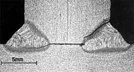
Two different crack initiation and propagation modes were observed for the load-carrying condition. Mode 1, which is shown in Fig.16a was observed in specimens tested at higher stress levels, whereas mode 2, which is shown in Fig.16b, was observed in specimens tested at lower stress levels. It can be seen from the figures that the geometry of the welds giving these two different crack modes was similar.
| a) high stress |
b) low stress level |
 |
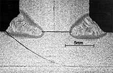 |
| Fig.16. Crack propagation in fatigue specimens tested at: a) high stress; b) low stress level |
Mode 1 has two different crack initiation points, namely the root of a weld and the toe of a weld. This is likely to have resulted from the fact that the fillet size of the welds was close to the critical fillet size for which crack initiation shifts from root side initiation to initiation at the weld toe. The fatigue crack in mode 2 initiates solely at the weld toe on the bottom plate.
The fatigue testing of T-joints in the non-load carrying condition showed similar results, i.e. a fatigue curve well above the design curves for MAG welding, and with a flatter slope. Both the fatigue tests thus showed that the fatigue properties of Nd:YAG laser-MAG hybrid welds had a closer resemblance to fatigue properties from laser welds that fatigue properties from MAG welds.
4. Conclusions
In this project, procedures were developed for Nd:YAG laser-MAG hybrid welding of T joints for shipbuilding applications as part of the European Union sponsored project ShipYAG. The main driver for applying hybrid welding was an expected reduction in distortion with a process that could tolerate the joint fit up accuracy expected in the shipyards.
From this work, the following conclusions could be drawn:
- Procedures have been successfully developed for making Nd:YAG laser-MAG hybrid welds in a T joint configuration for 4 to 5mm and for 10 to 12mm C-Mn steel.
- The procedures gave reproducible welds of acceptable quality and satisfactory mechanical properties, although higher carbon containing steels may necessitate increased heat input to achieve acceptable hardness levels.
- In many respects, the Nd:YAG laser-MAG hybrid welds gave mechanical properties comparable to those for laser only welding, e.g. overmatched strength and hardness in the weld zone and good fatigue properties. The fatigue resistance seems to be in excess of the design lines for arc welding.
5. Acknowledgements
The work performed in this project was part of the collaborative project ShipYAG, a collaboration between Bisiach & Carrù (Italy), CRF (Italy), Fincantieri Cantieri Navali (Italy), Force Technology (Denmark), IWA (Denmark),Lloyd's Register of Shipping (United Kingdom), the National Technical Universtiy of Athens (Greece), Odense Steel Shipyards (Denmark), RINA (Italy), Trumpf (Germany) and TWI (United Kingdom). It was funded by the European Commission under the GROWTH programme (contract number G3RD-2000-00251) and by in-kind contributions from the partners.
6. References
- Sepold, G. and Seyffarth, P.: Laserstrahltechnologien für den Schiffbau (Laser beam technologies for shipbuilding), Proceedings Schweissen und Schneiden Conference, September 1994, DVS Berichte 162, Bremen, Germany, p. 159-164 (1994)
- Sellerup, M.: Experiences of Laser Welding and Cutting in Hull Production, Proceedings International Institute of Welding on Welding in Shipbuilding Conference, September 1998, DVS Berichte 195, Hamburg, Germany, p. 25-27 (1998)
- Laser Beam Welding and Cutting at Blohm+Voss GmbH - brochure, Blohm+Voss, Hamburg, Germany.
- Seyffarth, P.: The Use of High-Power-Lasers in Shipbuilding, Proceedings International Advanced Metallic Materials and their Joining Conference, October 2004, Bratislava, Slovakia (2004).
- Shipbuilding Low Cost, Versatile and Safe Welding by YAG Laser Appliction (ShipYAG), EU-sponsored GROWTH project, contract number G3RD-2000-00251.
- Guidelines for the Approval of CO2-Laser Welding, Lloyd's Register of Shipping, March 1997.