Deformation Pattern Based Digital Image Correlation Method and its Application to Residual Stress Measurement
Jianxin Gao* and Haixia Shang
*Corresponding author
Paper published in Applied Optics, vol.48. issue 7, 2009. pp.1371 - 1381.
Abstract: To measure directly residual stresses by digital image correlation using hole-drilling, the deformation pattern which is governed by the residual stresses is used to affine transform the image captured after the object is deformed. If the values of trial residual stress components are properly chosen, the image after affine transformation will have a maximum similarity to the original image. This turns the residual stress measurement issue into a pure numerical computational process, which leads to the direct output of residual stresses. Validation tests have proved the viability of the approach. The proposed concept and principle could be extended to other specific measurement tasks with known deformation patterns.
Keywords: Digital Image Correlation, Deformation Pattern, Affine Transformation, Optimisation, Residual Stress, Stress Measurement
OCIS codes:
100.2000 Image processing: Digital image processing
120.4880 Instrumentation, measurement, and metrology: Optomechanics
1. Introduction
Residual stresses are an important issue for the structural integrity of welded components and structures. Currently, the strain rosette, hole drilling technique is widely used for residual stress quantification in industry.[1-3] This is a straightforward method that measures directly the strain released by the drilled hole. Residual stress is subsequently calculated from the strain. Since this technique requires the attachment of a strain rosette onto the object surface, there are some limitations in its industrial application. For example, the hole should be drilled with good positional accuracy. The location of the hole is known to affect the accuracy of the measured stress values. Only limited strain data are available which are the average over the strain pitch. Significant efforts had been made to address these issues in 1970s and 1980s. A detailed analysis of the errors associated with these issues was given by Scaramangas. [2]
Apart from strain gauge based techniques, non-destructive diffraction based techniques have also been developed for residual stress measurement. They include X-ray diffraction, neutron diffraction and other diffraction methods. These techniques have the capability of measuring 3D stress components in the bulk of the material. However, since they require the use of an X-ray or neutron source, which could be either hazardous to human safety or very expensive, their application in on-site engineering environments is rather limited. Therefore, there is a need to develop a technique that can be applied to measure residual stress on site in an engineering environment.
Optical techniques have long been applied to measure mechanical displacement and deformation of various materials and components. The main advantages of optical techniques are non-contact, full field measurement with high sensitivity. Optical techniques can be categorised into two groups, fringe based interferometric techniques and non-interferometric techniques. The former includes moiré, holographic and speckle interferometry, electronic speckle pattern interferometry and shearography, while the latter simply consists of image processing based techniques. Interferometric techniques usually offer high sensitivity and accuracy in displacement and/or deformation measurement.[4-6] Since they must use coherent light, most interferometric techniques tend to be prone to environmental disturbances during measurement. Their application to on-site measurement in an engineering environment has therefore been limited. An exception is the interferometric strain/slope rosette (ISSR) method proposed by Li et al,[7-9] which is insensitive to in-plane rigid body motions. This is normally used with ring-core cutting for releasing residual stress, which is usually more complex than hole-drilling. When used with hole-drilling, the stress calculation is more complicated due to the non-uniform release of residual stress.
Digital image correlation (DIC) is a well known non-interferometric technique, having the capability of measuring the displacement field of an object with an ordinary light source such as white light.[10, 11] Without the need to form an interferometric fringe pattern, the optical set-up of DIC is rather simple. These factors mean that DIC has the potential of being employed in an engineering environment. Considerable efforts have been devoted to using DIC in conjunction with the hole-drilling technique to measure residual stress.[12-14] However, in previous development work, DIC was simply used as a displacement measurement technique similar to interferometric optical methods. The conventional procedure for residual stress measurement starts with displacement measurement, followed by differentiation of the displacement field or other relevant numerical manipulations to obtain strain information, and finally calculates the stress values based on theoretical or numerical FEM models. There are two main shortcomings in this conventional approach. Firstly, the process for calculating residual stress is complex, and can only be carried out by professionals with a sound knowledge of mechanics and materials. It is therefore difficult for a non-professional to use this approach to measure the residual stress. Secondly, the sensitivity of the technique is relatively low. The minimum resolution of residual strain is reported to be around 3×10⁻⁴. [6, 12, 14]
This paper presents a novel approach to DIC for residual stress measurement to address the above shortcomings. Instead of using displacement components as the basic variables in conventional digital image correlation, residual stress components are taken as the direct variables. Each set of residual stress components corresponds to a specific deformation pattern. This deformation pattern as a whole is used to inversely affine transform the digital image captured after a hole is drilled onto an object under testing. Once the residual stress components are properly chosen, the digital image after inverse affine transformation will have the highest similarity to the digital image taken before the object is drilled, i.e. the transformation will recover the original image. This turns the stress measurement issue into a purely numerical computational process, i.e. a search for a set of residual stress components that will maximise the correlation between the original image and the inverse affine transformed image after hole drilling. This can be implemented through an optimisation procedure. Since the direct variables in such a numerical optimisation process are the residual stress components, the conventional stress measurement procedure in optomechanics, which involves the complex interpretation of a displacement field, is no longer required. This will facilitate the development of a compact system for residual stress measurement with ease of use for the operator. The proposed concept and principle shall not be limited to residual stress measurement, and could be extended to other specific measurement tasks with known deformation patterns.
2. Concept of deformation pattern based DIC
The central idea of the proposed approach is to use the intrinsic parameters of a measurement task as direct variables in the computation of the correlation coefficient between two images. A set of intrinsic parameters will define a specific type of mechanical behaviour of an object under investigation. For example, in a cantilever beam under point load and bending at the free end, the intrinsic parameters consist of two variables: the load force and the bending moment. In residual stress measurement, the intrinsic parameters are residual stress components. In both cases, the displacement field is governed by the stated intrinsic parameters.
Now let us describe the novel approach to the measurement of a specific type of mechanical behaviour. For simplicity and clarity, and without losing generality, we use the mechanical behaviour of a planar residual stress state released by a hole drilled in an infinite plate, as shown in Fig.1. In this case, the three residual stress components, σx, σy, τxy, are the intrinsic parameters. They are obtained by measuring the displacement field or strain when a small hole is drilled to locally release the residual stress. For the convenience of expression, both Cartesian coordinate system (x, y) and polar coordinate system (r, θ) are used in following sections. Based on the theory of elasticity, once a small hole is drilled, the following displacement field will occur[4, 13]:
Fig.1. Residual stress σx, σy, τxy released by a hole drilled on a plate
[1]
where u rs and v rs are the displacement components along the x and y axes, respectively, E is the elastic modulus, µ the Poisson's ratio, and
for plain stress status or x = 3 - 4µ for plain strain status.
The conventional approach to residual stress measurement is to solve the three unknowns σx, σy, τxy from a set of linear equations expressed in Equation (1) by measuring the displacement components urs and vrs at several locations. At least three linear equations should be generated:
[2]
where Di(x,y) is the ith displacement, and fx, fy, f xy are the associated coefficients derived from Equation (1). The residual stresses can be solved as:
[3]
Considering the inevitable error in each individual measurement, more displacement measurements at different locations are preferred. This results in a set of n (n>3) linear equations. By using a linear least squared technique, residual stresses can be solved with enhanced accuracy.
Our approach does not follow this conventional procedure. We know that the basic concept of DIC is a displacement search process which is based on the criterion of correlation between two images of an object corresponding to before and after its deformation. When a subset of pixels in one image is searched out in the other image, i.e. the correlation between the two subset images reaches the maximum, their coordinate difference is the measure of displacement. This concept of correlation search is adopted in our new approach. The difference is that the basic variables in the new search process are the residual stress components, not the displacement components. In the new approach, the task is to search for a set of intrinsic parameters (the residual stress components) which maximise the correlation between the original image and the inverse affine transformed image after hole-drilling. This can be implemented by an optimisation process which is purely a numerical computation problem.
The new approach takes full advantage of a known deformation pattern, which is related to a specific mechanism, in this case the release of residual stress by a drilled hole. A different set of residual stress components corresponds to a different deformation pattern. By looking at the deformation pattern over the entire region of interest in an image, we can make use of the overall information of the images, not just isolated displacements at limited locations. There is another advantage of this approach over the equation solving procedure described above. It is apparent that the effect of the residual stress on the released displacement is not uniform across the region of interest around the hole. The released displacements have maximum values along the border of the hole, and will decrease with distance from the hole centre. This means that the linear equation (1) at a different location should not be treated equally with the same weight. If equal weighs are used then the accuracy of the final solution will be significantly decreased if some of the displacement measurements are made at locations far from the hole centre. By focusing on the overall deformation pattern, such a weight issue does not exist in the proposed approach.
3. Algorithms of deformation pattern based DIC for residual stress measurement
Let (x, y) be the coordinate of the digital images acquired through an optical imaging system, and F and G the digital images corresponding to before and after the hole is drilled, i.e.
[4]
where M and N are the numbers of horizontal and vertical pixels of a digital image, respectively.
For image G, an inverse affine transformation is defined as:
[5]
where u rs and v rs are the displacement components released by a drilled hole as expressed in Equation (1), and (x', y') are the new coordinate system. In this way, the intrinsic parameters (residual stresses) are introduced in the inverse affine transform.
After the above inverse affine transformation, a new image G' can be formed:
[6]
The correlation between this new image G' and the original image F is calculated as:
[7]
where <...> denotes an ensemble average over the image domain. |C|≤=1, and C=1 only when F=G'.
It is obvious that the correlation is an explicit function of the pixel intensities of two images. The displacement field or intrinsic parameters are introduced implicitly by the use of affine transformation of the image coordinate system. Generally, the correlation is a function of the intrinsic parameters (σx, σy, τxy) in an implicit sense, i.e.
[8]
A different set of intrinsic parameters (σx, σy, τxy) will result in a different correlation value C. If the trial intrinsic parameters (σx, σy, τxy) are equal to the actual residual stress component, image G' will be exactly transformed back to the original image F when the digital sampling noises of the imaging system are negligible. This can be implemented by an optimisation process.
In reality, there are some more issues that need to be addressed when using DIC to measure residual stress. Firstly, in-plane rigid body displacement inevitably occurs during image acquisition before and after a hole is drilled onto the testing sample. It consists of rigid body shift, u 0 and v 0 , along the x and y axes respectively, and in-plane rotation ω. They are the result of either the accumulated deformation at the hole drilling location, or of the environmental disturbance during image acquisition. Secondly, out-of-plane displacement w 0 often exists too. It is the result of either the movement of the digital camera during image acquisition, or the accumulated deformation of the object. This out-of-plane displacement can have a significant effect on the accuracy of strain/stress measurement, because it will result in a change in image magnification during image acquisition. This is equivalent to imposing a virtual uniform extension or compression to the testing sample, depending on whether the object is moving towards or away from the imaging camera. Since the strain associated with a typical residual stress state is in the magnitude of tens to hundreds of micro strain, a slight out-of-plane displacement, say 50µm over an imaging distance of 100mm, would mean a virtual strain (500µe in the example, 1µε=10-6) that might be bigger than the actual strain values. Without addressing this virtual strain field, the direct stress/strain measurement would be meaningless.
To ensure the new approach works effectively, the above in-plane and out-of-plane displacement (u 0 , v 0 , w 0 , ω) should be taken into account in the correlation search process. Here for convenience and without losing generality, w 0 is defined as the relative change in the distance between the surface of the object and the imaging camera, i.e. the relative change in magnification of the imaging system. Therefore, the affine transformation becomes:
[9]
and the correlation has been a variational function of seven variables:
[10]
During the correlation search process, those trial rigid body displacements and residual stress components that maximise the correlation are regarded as the actual value for the measurement. Fig.2 shows the flowchart of the new search process.
Fig.2. Flow chart of correlation search for residual stress measurement
In practice, the whole search process is implemented by a two stage approach. The first stage involves only the detection of the bulk of the in-plane rigid body displacement field, i.e. only integer pixel rigid body shifts are considered. Once the bulk of rigid body displacement is obtained, it is compensated for by simply shifting the image G backwards accordingly. This paves the way for the next stage of a refined search process, focusing on the fine scale differences between the two images. These differences consist of both the remainder of the rigid body displacement field (fractional pixel) and the results of stress, deformation, and/or environmental disturbances. Once this second stage is done following the flowchart in Fig.2, residual stress measurement is complete.
4. Optimisation scheme for the correlation search process
Since there are seven variables in the fine search process, the key to success is to design a proper optimisation scheme such that the possibility of being trapped in local maxima is reduced while the computational cost of finding the global maxima of correlation is not too high to be carried out with a conventional computer.
Different optimisation methods have been used in our system. These include the Newton-Raphson method, the Marquardt-Levenberg method, the modified gradient based optimisation method, and various bounded exhaust search methods. Although these well-known optimisation methods worked effectively in the majority of our tests, there were still occasions that they would lead to false measurement results. This is mainly due to the fact that, once the bulk of the rigid body displacement is detected and compensated for, the correlation tends to be very high, exceeding 90% and close to 1. Any further changes in rigid body shift, rotation and stress related deformation will only slightly enhance the correlation. As a result, there could be many local maxima with close correlations in the vicinity of the true solution, especially when the electronic noise within the digital image pair is relatively large. Therefore, it seems there is no single optimisation method that will work ideally for our purposes under all circumstances.
In order to minimise the possibility of a false optimisation result, a bounded exhaust search scheme is also adopted in our system. The bound for in-plane displacement (u, v) is within ±0.1 pixel, ±1% for in-plane rotation ω and out-of-plane displacement w 0 , and ±2% for nominal stress components (σx/E, σy/E, τxy/E). The search steps for each variable vary, following a coarse-to-fine search procedure, such that the total number of correlations is small enough (1,000 to 20,000) for a conventional computer to carry out the whole process within a reasonable period of time. Detailed work and results will be provided in a future publication.
5. Validation tests for residual stress measurement
(A) Test sample and experimental set-up
Two test samples were made to validate the proposed method; one was with aluminium alloy 2024, the other steel. Fig.3 shows the geometry of the samples and Fig.4 is the experimental set-up. A test rig was also designed and fabricated to hold the test sample with minimal bending effect during extension. The extension was implemented manually by adjusting a bolt on top of the test rig using a wrench. Two strain gauges were bonded onto the sample surface to monitor the real horizontal and vertical strains as a result of the manual extension. The strain gauges were sufficiently distant from the holes on the sample, so that their readings provided the far field uniform strain components within the sample. During testing, a Canon 100mm F2.8 EF Macro USM lens was used to record digital images. The surface of the sample was sprayed with black paint in order to form speckle-like images.
Fig.3. Geometry of the test samples. Residual stresses equal to the uniaxial stress applied by axial extension and unloading
Fig.4. Experimental set-up for validation test. A Canon EF-S 60mm f2.8 USM Macro lens was used to record digital images. The surface of the sample was sprayed with black paint to form a speckle-like appearance
For simplicity of the validation tests, two holes were pre-drilled on the test samples. During a validation test, the sample was extended successively, from 0µε to 250µε, to 500µε, ..., to 2000µε. Afterwards, the sample was unloaded gradually to 10µε. At each loading/unloading step, a pair of images was taken and saved to a computer. Table 1 shows the strain gauge readings during a uni-axial extension test on an aluminium sample. Digital images are recorded at each load/unload step and are saved in the computer. By selecting any two images corresponding to different load steps, various relative stress changes can be formulated. This allows us to simulate different residual stress levels ranging from compressive stress to tensile stress, so that comprehensive validation tests on the proposed method can be made.
Table 1. Experimental recordings during uniaxial extension test on an aluminium sample. Strains were measured by strain gauges which were bonded on the reverse of the specimen.
| Test sequence | Longitudinal strain (µε) | Transverse strain (µε) |
|---|
| 1 |
2 |
0 |
| 2 |
244 |
-81 |
| 3 |
497 |
-164 |
| 4 |
741 |
-243 |
| 5 |
998 |
-326 |
| 6 |
1495 |
-487 |
| 7 |
2004 |
-650 |
| 8 |
1515 |
-495 |
| 9 |
1000 |
-329 |
| 10 |
749 |
-248 |
| 11 |
501 |
-168 |
| 12 |
254 |
-88 |
| 13 |
2 |
-7 |
(B) Measurement results
The actual deformation around the hole of the test sample under axial loading is the superimposition of two deformation fields. The first is the deformation field of a plate without a hole under uni-axial extension/compression. The second is a residual stress associated with the deformation field described by Equation (1). Here the residual stress has only one component which equals the axial stress. By taking into account the superimposed deformation field in the image processing software, stress results can be calculated directly. When used for measuring actual residual stress, the first part of a far field uniform stress shall be excluded and all the other settings of the algorithms remain the same.
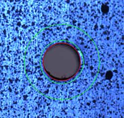
The measurement procedure is as follows. (1) Load a configuration file which contains the basic parameters of the measurement, namely the material properties, the diameter of the hole and thickness of the sample. (2) A pair of images is loaded into the software. The image scale factor is calculated automatically by measuring the diameter of the hole in pixels which is then converted to the actual dimension. (3) Locate the centre of the hole by simply adjusting a circle representing the hole to coincide with the boundary of the hole, as shown in Fig.5. This enables the centre to be located with high accuracy, usually within half a pixel. (4) Select a region of interest (ROI) around the hole. This is done by adjusting the radii of an outer and an inner circle such that the band in between is the ROI of selection whose pixels are used in the subsequent affine transformation to calculate the residual stress. (5) Click the button on the menu to start the correlation optimisation process to directly calculate the stress components. It takes between half a minute and 10 minutes to complete the whole computational process, depending on the total number of pixels of the ROI selected and the optimisation strategy used.
| a) Locate the centre of the hole, and designate ROI by adjusting the inner and outer circle. |
b) Selected ROI is displayed as grey-shaded (green) area |
 |
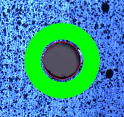 |
| Fig.5. Image initialisation. The hole diameter is 2mm. |
The result of each measurement is the rigid body in-plane displacement (
u,
v) and rotation ω, the relative out-of-plane displacement
w 0 , and the three nominal residual stress components (σ
x/E, σ
y/E, τ
xy/E). Extensive validation measurements have been made to test the accuracy, sensitivity, reliability and repeatability of the proposed method. By selecting images taken at different loading steps listed in
Table 1, we can form various image pairs which correspond to various stress differences. These image pairs were loaded into the measurement system, and residual stresses were measured and compared to their actual values from strain gauge readings. In this way, the sensitivity and repeatability of the measurement system can be evaluated. It is found that the overall nominal stress resolution (σ/E) is 1~2×10
-4, while the repeatability is about 1.5×10
-4.
Fig.6 shows some of the measurement results compared with actual strain results deduced from the strain gauge readings at different loading combinations. The standard deviation of nominal stress measurement is 1.15×10
-4. The success rate of a single measurement is around 95%, which will be discussed further in the next section.
Fig.6. Comparison of measured residual stress by the proposed method with actual strain gauge readings. The standard deviation is 1.15×10⁻⁴
As a comparison to conventional approaches using DIC, reported values of the standard deviation of measured residual stress (nominal σ/E ) lie between 2×10⁻⁴ and 3×10⁻⁴.[12,14] The results from the novel approach show a smaller deviation, which reflects the benefit of taking into account more of the available information during residual stress calculations.
6. Discussion
(A) Direct measurement of residual stress
The displacement field is the direct focus in most optical techniques for stress/strain measurement. The current approach, however, has shifted that focus from displacement to stresses or other driving forces that cause the displacement field. This is equivalent to looking at the overall deformation pattern associated with a specific type of mechanical behaviour that is represented by a set of intrinsic parameters, rather than making isolated displacement measurements at limited locations within the field of view. The intrinsic parameters govern the deformation pattern of an object under investigation, and thus are the prime concern of a measurement task. By employing an optimisation strategy, the task of stress/strain measurement can be turned into a correlation search process. That is, to find a set of intrinsic parameters that, after being used to perform an affine transformation, will best recover the deformed digital image to its original one.
The direct output of the proposed approach is no longer the displacement field but the intrinsic parameters themselves such as stresses. This means that the complicated displacement interpretation such as fringe order counting or displacement differentiation which is essential in most other optical methods can be avoided. Once the intrinsic parameters are found, the associated deformation patterns are already determined. So the task of stress/strain measurement would only involve some mouse clicks. This will pave the way for the development of a compact portable stress/strain measurement system that can be operated by non-professionals whose knowledge about strain/stress and mechanics of materials is at a minimum.
It should be noted that the above description only involves through hole drilling with a residual stress that has a uniform depth distribution and within a small elastic strain limit. As there are classical analytical solutions available, the implementation of the proposed method is relatively simple. For incremental hole-drilling where explicit analytical solutions do not exist for the deformation patterns, both numerical FEM results and experimental measurements will be used to establish a numerical database so that deformation patterns corresponding to different hole depths are available. This future work will be based on the work by Ponslet and Steinzig in 2003.[15] With such a numerical database or a look-up table, the principle of DPDIC can be implemented in a similar way.
It is also worth noting that, in real measurements with hole drilling, the camera must be kept unchanged before and after a hole is drilled. This can be done by using a macro lens with a large enough working distance to allow the drilling head to be put in place. Furthermore, to ensure the success of DIC, the object surface must be free of debris from the drilling process. This can be done either by covering the surface using a plastic tape or by cleaning the debris during the hole-drilling process using an air blower or vacuum cleaner.
(B) Credibility of the measurement
Correlation is the measure of similarity between two images or image subsets. For images that consist of randomly distributed intensities, the possibility of one subset completely matching the other, i.e. the correlation equals 1, should be zero. Only two identical image subsets will have the maximum correlation of 1. However in reality, there is always electronic or other noise during image acquisition. An example is shown in Fig.7. As a result, the correlation between two image subsets in two different images will never reach 1.
Fig.7. Intensity variations. Image 2 was recorded 30 seconds after the acquisition of image 1. The intensity distribution along a line shows the intensity variations due to electronic and other noise during image acquisition
On the other hand, the correlation between two uncorrelated image subsets always lies between -1 and 1, and will never reach 1. But the possibility that the correlation between two uncorrelated image subsets is very high or close to 1 does exist, although the possibility is very low. Combined with the effects of electronic and other noise, there is always a possibility that no matter how big the correlation is, the corresponding two image subsets could still be physically uncorrelated. In other words, those correlations that correspond to the true solution would not necessarily be a global maximum. When this happens, it means the optimisation search process fails, i.e. the final output of the stress measurement might be an outlier, or incorrect.
One way to suppress such a failure rate is to swap the image sequence and perform the whole measuring process again. This means that the affine transformation is performed on the original image F, and the optimisation process becomes the search for a set of trial stress components that will enable the affine transformed initial image to best resemble the final image G. If the new calculation result is close to the previously obtained one within a reasonable margin, both measurements have high credibility and can be retained. Otherwise, the results should not be used, and further measurements are needed where an expanded ROI must be used to take into account even more pixels within the recorded images. However, based on the validation tests (over 300) carried out, the failure rate is less than 5%. Further attempts to reduce this failure rate are ongoing.
(C) Optimisation strategy
As described above, the current approach has turned a stress measurement task into an optimisation process based on the criterion of correlation. Generally speaking, correlation is very sensitive to rigid body displacement components (u 0 , v 0 , w 0 , ω) and stress components (σx/E, σy/E, τxy/E). This means that a slight change in (u 0 , v 0 , w 0 , ω) and (σx/E, σy/E, τxy/E), say 0.1, will cause a significant change in correlation, typically from above 0.9 to below 0.8. However, in stress/strain measurement, strains are normally in the magnitude of 10-4 (100µε) or even smaller. Therefore, it is anticipated that a stress/strain measurement system can have a reliable sensitivity of strain measurement up to 10-4 or 10-5. In this sense, the correlation is not sensitive enough for very small changes in stress/strain to be distinguished, especially at the plateau of a maximum. Fig.8 shows such a scenario, in which the correlation only varies negligibly from 0.99178 to 0.99187 when the in-plane displacement has a change of 0.03 pixels (~0.5µm in real dimension). For strain/stress sensitivity, the correlation varies from 0.9914 to 0.9919 when the nominal stress undergoes a change of 300µε.
8a) Correlation vs. displacement
8b) Correlation vs. nominal stress
Fig.8. Correlation distribution in the vicinity of a maximum
Investigation on the correlation distribution showed that the energy landscape of correlation near its global maximum is usually rough, with many sub-maxima in the surrounding area. Since the correlation is the variational function of seven parameters (u 0 , v 0 , w 0 , ω, σ x , σ y , τ xy ), the actual landscape in this seven-dimensional space must be even more complicated. This is probably the main reason why there does not exist a single optimisation strategy that will work at all times. Considering the extraordinary computational costs in some well know optimisation strategies such as the Monte Carlo method, exhaustive search with specifically designed boundaries and steps might be the sub-optimal practical solution. More work on optimisation strategy is needed to further improve the proposed technique.
7. Conclusions
A novel deformation based digital image correlation method is proposed. It uses intrinsic parameters that represent a particular mechanical behaviour of an object under investigation as the direct variables in correlation computation. Examples of such intrinsic parameters are the stress components in the measurement of residual stress released by a hole-drilling technique. Each set of such intrinsic parameters corresponds to a specific deformation pattern, which as a whole is used to affine transform the digital image captured after the object is deformed. This turns the stress measurement issue into a purely numerical computation process, i.e. a search for a set of intrinsic parameters that will maximise the correlation between the inverse affine transformed image and the actual original image.
The proposed approach is implemented through an optimisation procedure. Since the direct variables in such a numerical optimisation process are the intrinsic parameters such as stress components, the conventional stress measurement procedure in optomechanics which involves the complex interpretation of displacement field is no longer required. This will facilitate the development of a compact system for a specific measurement requirement with ease of use for the operator. Validation tests have proved the viability of the new approach, and the sensitivity for residual stress measurement has been improved. The proposed concept and principle is not limited to residual stress measurement, and could be extended to other specific measurement tasks with known deformation patterns.
As a first effort to use the proposed concept in residual stress measurement, only the simplest case is considered in this paper, i.e. through hole drilling with a residual stress with uniform distribution along depth, within a small elastic strain limit. To fulfil the full potential of this new technique, much work needs to be done. This includes the design of a better optimisation strategy, further applications to generic surface residual stress measurements, the extension of DPDIC to address depth variant residual stress measurement with incremental hole-drilling, and the inclusion of the plastic effect when the locally concentrated strain exceeds the yield strength of the material. In addition, various optimisation methods will be adapted so that the possibility of being trapped in local maxima is minimum while the computational cost of finding the global maxima of correlation is not too high to be carried out with a conventional computer.
Acknowledgement
The authors would like to thank colleagues, Dr. Daowu Zhou and Dr. Simon Smith, for their valuable help and discussions on this work.
References
- E.M. Beaney and E. Proctor, A critical evaluation of the centre hole technique for the measurement of residual stresses. Strain Vol.10: pp.7-14, (1974)
- A.A. Scaramangas, R.F.D. Potter-Goff and R.H. Leggatt, On the correction of residual stress measurements obtained using the centre hole method. Strain Vol.18: pp.88-97, (1982)
- P.V. Grant, J.D. Lord and P. Whitehead, NPL Good Practice Guide No. 53 - Issue 2. The Measurement of Residual Stresses by the Incremental Hole Drilling Technique, (2006)
- J.B. Zhang and T.C. Chong, Fiber electronic speckle pattern interferometry and its applications in residual stress measurements. Appl. Optics, Vol.37: pp.6707-15, (1998)
- F.V. Diaz, G.H. Kaufmann and G.E. Galizzi, Determination of residual stresses using hole drilling and digital speckle pattern interferometry with automated data analysis. Optics & Lasers in Engineering. Vol.33: pp.39-48,(2000)
- M. Steinzig and T. Takahashi, Residual stress measurement using the hole drilling method and laser speckle interferometry. Part IV: Measurement accuracy. Experimental Techniques, Vol.27: pp.59-63, (2003)
- K. Li and W. Ren, Application of ring-core and optical rosettes to measure residual stress distribution with depth-part I: theory. ASME Journal of Applied Mechanics, Vol. 74: pp.298-306, (2007)
- W. Ren and K. Li, Application of ring-core and optical rosettes to measure residual stress distribution with depth-part II: experiments. ASME Journal of Applied Mechanics, Vol. 74: pp.307-314, (2007)
- T. Tjhung and K. Li, Measurement of in-plane residual stresses varying with depth by the interferometric strain/slope rosette and incremental hole-drilling. ASME Journal of Engineering Materials & Technology, Vol.125:pp.153-162, (2003)
- W.H. Peter and W. F. Ranson, Digital imaging technique in experimental stress analysis. Opt Eng, Vol.21: pp.427-431, (1982)
- B. Pan, H.M. Xie, B.Q. Xu and F.L. Dai, Performance of sub-pixel registration algorithms in digital image correlation. Measurement Science & Technology, Vol.17: pp.1615-1621, (2006)
- D.V. Nelson, A. Makino and T. Schmidt, Residual stress determination using hole drilling and 3D image correlation, Experimental Mechanics, Vol.46: pp.31-38, (2006)
- M.J. McGinnis, S. Pessiki and H. Turker. Application of three-dimensional digital image correlation to the core-drilling method. Experimental Mechanics, Vol.45: pp.359-67, (2005)
- J.D. Lord, D. Penn and P. Whitehead, The application of digital image Correlation for measuring residual stress by incremental hole drilling, Applied Mechanics & Materials, Vol.13-14: pp.65-73, (2008)
- E. Ponslet and M. Steinzig, Residual stress measurement using the hole drilling method and laser speckle interferometry. Part II: Analysis techniques. Experimental Techniques, Vol.27: pp.17-21, (2003)