Faye Smith
Presented at Composites Processing 2004, CPA, Bromsgrove, UK, 23rd April 2004
Abstract
The aim of the development work described here was to investigate whether the application of a new surface treatment technique, called Surfi-Sculpt TM , into a new joining system, called Comeld TM , would improve the mechanical performance of joints between composite materials and metals. The data generated showed that Comeld TM joints prevented sudden bond-line failure occurring. ComeldTM joints also gave a more progressive, and therefore detectable, failure mode than the control joints and absorbed more than twice as much energy before failure than the control joints.
1. Introduction
The differences in design and manufacturing processes used for structures made from fibre reinforced polymeric composites materials compared to the same structure made from metal are considerable. Cost implications due to process change, lack of in-service data, general mistrust of the unknown and conservatism are amongst the factors that have previously lead to lengthy delays between materials innovations in the world of composite materials and their implementation in appropriate industry sectors.
However, performance benefits eventually win through and these materials are now exploited in a variety of established production components and structures in applications in industry sectors such as aerospace, marine, motor sport,military and specialist construction.
In order for full exploitation of composite materials to occur a materials engineer needs to be confident that the specific material property offered by the composite material can easily be incorporated into a structure, made from many materials (e.g. metals, plastics, ceramics etc.) at the exact position required. This requires joining of composite materials to a wide range of materials to be easily achievable. Properties of the joint should be known, consistent and reproducible, easily inspected and retained over a loading history similar to that expected in service.
There are currently three commonly used techniques for joining of composite materials to themselves and other materials; adhesive bonding, mechanical fastening and a combination of bonding and fastening.
It has been known for many years that bonded joints, containing composite materials, can be designed such that the adhesive sustains loads greater than the strength of the parent material. [1] Correctly designed [2] and manufactured adhesively bonded joints do not exhibit failure due to fatigue loading. [3] Various rules can be employed during the design of adhesively bonded joints to limit the amount of plastic behaviour of the adhesive as, in certain joint geometries, this may promote premature fatigue failure. There are also design principles that take into account difference adherend properties such as coefficient of thermal expansion mismatches. The likelihood of failures caused by environmental degradation of the interface between the adhesive and the bonding surface can be reduced with correct surface preparation techniques. The techniques used depend on the materials to be joined and an example of the range offered for a specific material combination is given in reference [4] . Despite the detailed design and manufacturing knowledge that exists, in-service experience, which shows that some bonds provide excellent service whereas others fail or require extensive maintenance over a short service life,has led to lack of confidence in adhesive bonding technology.
The use of mechanically fastened joints in isotropic and ductile materials, such as metals, is well understood. In these materials, yielding reduces the stress concentrations around bolt holes. Numerous studies on mechanical fastening of composite materials have shown that there is very little relief from the stress concentrations around the holes. Unidirectional composites are essentially elastic to failure, therefore the efficiency of joints in this material is very low. However, if the degree of anisotropy is reduced around the hole, for example by incorporating fibres in multiple directions, pseudo-plastic behaviour, in the form of disbonding, delamination and matrix cracking,can locally alleviate the most severe stress concentrations. Careful design of the joint and choice of composite material lay-up can mean that the tensile and shear modes of failure are suppressed and maximum joint strength is attained in a bearing mode of failure. [5] The brittle nature of composite materials also means that there is virtually no capability for redistribution of load if one fastener in an assembly fails. It is therefore important to calculate accurately the load sharing between fasteners and to identify the most critically loaded position.
If weight is not an issue, mechanically fastened joints containing composite materials can be designed to compete with adhesively bonded joints. Mechanically fastened joints can also be disassembled relatively easily in comparison to adhesively bonded joints, which makes them attractive for inspection, repair and recycling purposes amongst others. This means that, in industry sectors used to dealing with metals, mechanical fasteners have been commonly used to join composite materials to themselves and other materials.
Table 1 [6] presents the advantages and disadvantages of adhesive bonding when compared to mechanical fastening.
In many cases, in order to address the limitations of both joining techniques, hybrid joints containing both adhesives and mechanical fasteners are used. Such an approach defeats the main objectives of using the composite material i.e. size, weight and cost savings. The well-understood properties of aerospace alloys become attractive again and limit the positive benefits of composite systems.
A proprietary material surface treatment technique and joining process developed recently at TWI [7] , offers the potential for joints to be made between fibre reinforced plastic (FRP) composite materials and metals with enhanced performance. It is expected that this joining technique will allow joint design to be revolutionised by overcoming some of the problems associated with adhesive bonding and mechanical fastening of composites to metals.
Table 1 Advantages and disadvantages of adhesive bonding compared to mechanical fastening.
| Advantages | Disadvantages |
|---|
- Ability to form lightweight, strong and stiff structures.
- Ability to join dissimilar materials
- Ability to efficiently join thin-sheet materials
- Improved stress distribution
- Good fatigue properties due to improved stress distribution
- Galvanic corrosion minimised by non-conducting interlayer
- Smooth surface finish
- Bonding process can be automated.
|
- Cannot be easily dissembled
- Residual stresses may be created due to mismatches in coefficient of thermal expansion
- Limits to thicknesses joined with simple configurations
- Sensitive to peel or through-thickness stress
- Poor resistance to elevated temperature
- Prone to environmental degradation under severe conditions
- Flammability and toxicity problems
- Inspection can be difficult.
|
2. COMELD TM joints.
The following sections describe some of the development work that has been performed at TWI into the new proprietary material surface treatment technique, called Surfi-Sculpt TM [7] , and its application in a joining process called Comeld TM . The material combinations and composite processing route demonstrated here were chosen to appeal to certain industry sectors. Further research has demonstrated that the technology described is equally applicable to other metals, composite materials, processing routes and therefore industry sectors.
2.1. Specimen preparation
The two joint geometries chosen to be tested are shown in Figure 1.
For each joint type, ten stainless steel specimens were machined to the required shape for the joint. Five of these specimens were grit blasted, to be used to create control joints, and five treated using the proprietary material surface treatment technique Surfi-Sculpt
TM , to be used to create Comeld
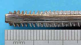
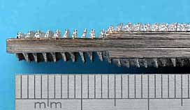
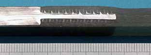
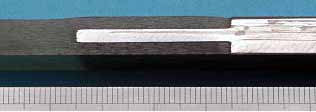
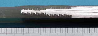
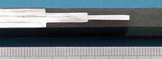
TM joints. Examples of the surface created using this new treatment are shown for each joint type in
Figures 2a and 2b. This surface treatment can be used to produce metal protrusions (known as proggles) in a variety of shapes and sizes on the material surface. In this case they have been produced with an approximately constant cross-section and leaning away from the direction in which load was to be applied to the joint.
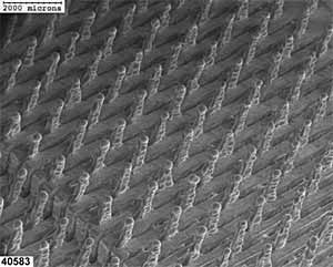
Figure 2c shows a SEM image of a double step stainless steel specimen with the surface treatment. It can be seen that for every proggle there is a corresponding hole or slot in the metal. The machined step in the joint is still clearly visible in the lower left hand corner of the picture and has not been altered in any way by the treatment. Immediately prior to manufacture of the joints, all the stainless steel specimens were degreased and etched with an oxalic/conc. sulphuric acid etchant.
| a) Single step, treated stainless steel |
b) Double step, treated stainless steel |
 |
 |
 |
c) SEM image of double step, treated stainless steel |
| Fig.2. Surface treatment using the Surfi-Sculpt TM process |
For both joint designs and both the control and Comeld TM
specimens, the joint was manufactured by lay-up of preforms of 400g/m
2 plain woven E-glass fabric (Carr Reinforcements) onto the metal specimens, followed by vacuum infusion of polyester resin (Crystic 489PA) into the glass fabric. The lay-up and preform details are shown in
Figure 3 and
Table 2. A schematic of the resin infusion process is shown in
Figure 4. The line of symmetry is included as two sets of specimens (the control and ComeldTM specimens) were infused in the same infusion. For clarity, only one set is shown. For all the specimens produced here, the resin used acted as both the matrix of the composite material and the adhesive for the joint, although in other joints an additional adhesive layer may be required at the bond-line.
Table 2 Description of preform layers
| Preform layer | Stacking sequence and orientation |
|---|
| 1A |
(0/90) 8 |
| 1B |
(0/90) 9 |
| 2A |
(0/90) 6 |
| 2B |
(0/90) 3 |
| 2C |
(0/90) 7 |
Following infusion of the resin, the laminate was cured for 19 hours at 25°C and postcured at 40°C for 21 hours. Figure 5 shows the joint region of selected specimens.
| 5a) Single step, Comeld TM joint |
5b) Single step, control joint |
 |
 |
| 5c) Double step, Comeld TM joint |
5d) Double step, control joint |
 |
 |
| Fig.5. Infused joints |
Figure 6 shows an optical micrograph of a joint in which the proggles of the stainless steel can be seen to interact with the glass fibre reinforced polyester (GFRP). The stainless steel has been overexposed in the image, and therefore appears white, in order that the glass fibres and polyester resin can be distinguished. It can be seen that the proggles extend into the glass fibre layers and the polyester resin extends down to meet the stainless steel with no voidage present. The specimen has been cut in such a manner that on the bottom surface of the stainless steel the holes that extend into the metal have been dissected. The dotted white line shows the surface of the stainless steel specimen and therefore where the holes start. The discolouration within the holes is due to the irregular shape of the holes.
2.2 Testing and results
Four Comeld TM and four control specimens for each joint type were loaded in tension at the rate of 1mm/minute until failure. Representative load-displacement curves for the single step and double step joints are shown in Figure 7 and Figure 8 respectively.
3. Discussion
Figure 5 and Figure 6 show that Comeld TM joints between stainless steel and glass fibre reinforced polyester composites material were successfully manufactured using vacuum infusion with no visible voidage.
The load displacement curves, shown in Figure 7 and Figure 8, demonstrate that the Comeld TM joints tested had a significantly greater load carrying capability than the corresponding control joints. The area under the load-displacement curves correspond to the energy absorbed during failure of the specimens. For both types of joints, the energy absorbed by the Comeld TM joint was more than double that absorbed by the control joint.
Figures 9a and 9c show that in the control specimens, failure occurred at the bond-line. These failures were very sudden, as indicated by the sharp change in slope in the corresponding curves (the solid lines) in Figures 7 and 8. There was very little damage to the metal or composite substrates.
In the Comeld TM specimens, the bond-line did not fail at low loads, therefore the joint was able to reach loads at which damage was seen to occur in the composite material. Damage was visible before failure as whitening of the composite caused by matrix cracking. It can also be seen from Figure 10a and b that there was deformation of the metal proggles before failure of the composite. As previously stated, the proggles had been designed to lean in the opposite direction to the load applied ( Figure 10a). After failure of the joint the proggles could be seen to be leaning in the same direction as the load applied ( Figure 10b). The Comeld TM specimens eventually failed due to shear failure of the composite just outside the section of composite that contained the proggles as shown in Figure 10c. The damage in the metal and composite described above contributed to the additional area under the graph and therefore extra energy absorbed during failure when compared to the control specimens.
An important factor to note was that failure of the Comeld TM specimens was more progressive than the sudden failure of the control specimens. Noise was heard from the damage generated in the composite material before failure of the joint, the load-displacement graphs exhibited greater changes in slope than seen in the control joints and at final failure the load drop-off was less sudden. In the case of the single step specimens, as shown in Figure 7, after the initial drop in load, the joint retained a small amount of load carrying capability for a short time. All these indications of damage occurring to a joint could aid in-service detection of a problem in a structure before sudden failure occurred.
4. Conclusions
The development work described has demonstrated that the application of a new surface treatment technique, called Surfi-Sculpt TM , to a new joining system, called Comeld TM , improves the mechanical performance of joints between composite materials and metals in the following respects:
- Comeld TM joints had a higher load carrying capability than control joints.
- Comeld TM joints absorbed more than twice as much energy as the control joints before failure.
- Comeld TM joints failure via a more progressive failure mode than the control joints.
5. Future work
Similar development work performed by TWI on alternative material combinations has also demonstrated improved mechanical performance of Comeld TM joints over control joints. TWI is therefore continuing in-house development of both Surfi-Sculpt TM and Comeld TM .
In order to accelerate the development of this new technology in areas directly relevant to industry, TWI is proposing a Group Sponsored Project in which Sponsor companies direct the research being performed and design the demonstrator joints to be tested. For more information on this project or any other technical aspect of Comeld TM please contact Ewen Kellar, ewen.kellar@twi.co.uk. For more information on Surfi-Sculpt TM , please contact Bruce Dance, bruce.dance@twi.co.uk
6. References
- Hart-Smith L J: 'Adhesive bonded single lap joints'. NASA CR 112236. January 1973.
- Hart-Smith L J: 'Design of adhesively bonded joints'. Joining fibre-reinforced plastics. Edited by F L Matthews. Elsevier Applied Science. 1987, pp.271-311. ISBN 1-85166-019-4.
- Thrall E W Jr: 'Bonded joints and preparation for bonding'. Proc. AGARD?NATO Lecture Series Number 102. 1979:5-1, 5-89.
- Molitor P, Barron V and Young T: 'Surface treatment of titanium for adhesive bonding to polymer composites: a review'. International Journal of Adhesion and Adhesives 21. 2001, pp.129-136.
- Collings T A: 'Experimentally determined strength of mechanically fastened joints'. Joining fibre-reinforced plastics. Edited by F L Matthews. Elsevier Applied Science. 1987, pp.9 - 63. ISBN 1-85166-019-4.
- Tong L and Steven G P: 'Analysis and design of structural bonded joints'. Kluwer Academic Publishers. 1999. ISBN 0-7923-8494-6.
- International Patent Publication Number WO 2004/028731 A1. 'Workpiece Structure Modification.' Applicant: The Welding Institute. Inventors: Bruce Guy Irvine DANCE and Ewen James Crawford KELLAR.
Acknowledgements
TWI would like to acknowledge the work performed at the Department of Materials at Queen Mary, University of London on vacuum infusion of Comeld TM joints. Thanks also to Bruce Dance for the application of Surfi-Sculpt TM to the stainless steel specimens.