Amin Muhammed and Julian Speck
Dr Amin Muhammed (amin.muhammed@twi.co.uk) is a principal integrity engineer, who undertakes a range of risk and reliability assessments on safety-critical structures.
Julian Speck (julian.speck@twi.co.uk) is TWI's structural integrity department manager, responsible for FFS and RBI projects and development activities.
Paper published in Inspectioneering Journal, May/June 2005 Volume 11, Issue 3
Code requirements
Current BSI and ASME codes for the construction of pressure vessels, boilers and piping specify that post-weld heat treatment is required if the thickness of the components being welded exceeds a specified value. This value depends on the type of material being used, and varies from code to code. An alternative procedure is available for deciding whether or not PWHT is necessary to avoid the risk of failure by fracture. This involves conducting a fracture mechanics assessment using procedures such as those in BSI 7910 (or API 579). The use of these procedures is permitted in the British pressure vessel standard BS PD 5500:2003.
Alternative to code rules
Welding thick walled components generates residual stresses that can be the cause of failure mechanisms such as brittle fracture and stress corrosion cracking. A criterion for PWHT based on a fracture mechanics assessment is more complicated than the code criterion of thickness alone. It may at first seem unlikely that designers, owners or certifying authorities would abandon the thickness-based criteria in favour of a more complicated approach. However, there are cases when PWHT is a code requirement but it may be considered unnecessary, excessively expensive, or practically impossible. In these cases, a fracture mechanics assessment may be used, subject to the agreement of the concerned parties. A fracture mechanics approach is based entirely on avoidance of failure by fracture or plastic collapse, Fig.1. Inspection engineers should also give consideration to the influence of heat treatment on avoiding other mechanisms such as fatigue and stress corrosion cracking, before adopting this approach.
Fig. 1. Fracture mechanics assesses the combined effects of flaw size, material properties and stresses acting on the flaw
Another Option: 'Patch' PWHT
When a component is too large to be furnace heat treated, local heat treatment of a circumferential band is allowed. Both API 570 and AWS D10.10 allow for the possibility of local heat treatment band on components, subject to various precautions. (British codes specify the size of local 'heated band' and American codes specify the size of the 'soak band'). The ASME B&PV Code will allow the width of the patch to vary provided the resulting temperature gradients are not harmful.
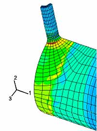
The severity of the resulting residual stresses due to temperature gradients from varying patches can be investigated using finite element analysis (FEA). The acceptability of any proposed variation in a soak band (eg. variable width, band shape, etc), can then be easily determined by evaluating the magnitude of the calculated residual stresses. That is (for a particular joint geometry), the magnitude of residual stress calculated by FEA, after modelling the code rules, versus the calculated stresses after modelling the proposed variation, Fig.2.
 |
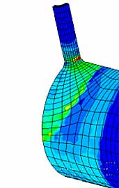 |
| Fig. 2. Residual stress after PWHT: full circumferential band (left) versus triangular patch (right) |
|
An FEA approach can be used at the time of original fabrication or in-service repair. The FEA should model the material properties in an elastic-plastic manner and allow stress relaxation during PWHT, as well as account for the initial stresses caused by welding. Experimental measurement of the residual stresses after patch PWHT will also be required to validate the results obtained from 'patch' PWHT.
A fracture mechanics case study
Fracture mechanics analysis is based on a consideration of the stresses acting at critical locations in a structure, the local geometry, the mechanical properties, the size of flaws (which may have escaped detection or been detected but left un-repaired after NDE), and the fracture toughness of the parent metal, weld metal and HAZ.
A boiler operator wished to waive PWHT of a stub-to-header weld repair. The parent material was 2¼Cr½Mo steel. The header collects steam from the boiler superheater via several hundred separate boiler tubes, Fig.3. The tubes emerge vertically from the furnace and each tube is welded to a shorter length of tubing ('the antler'), which is welded to a short stub tube, which is welded directly to the header. The stub tubes are welded to the header in the fabrication works.
Fig. 3. Boiler header and tube assembly
PWHT of the stub-to-header welds (along with the header welds) in the fabrication works is not excessively difficult or expensive. The stub-to-antler welds can be made on site (or in the fabrication works) and do not normally require PWHT (even for 2¼Cr½Mo) because they are thin sections.
However, PWHT of a single stub to header replacement (repair) during service is cumbersome. Such PWHT requires uniform heating of a cylindrical band around the header circumference. This is complicated by the many tubes protruding from the header, and the operation may cause an expensive delay to a repair outage.
Assumed flaws
To justify the boiler repair without PWHT, hypothetical flaws were assessed, Fig.4:
- Surface and embedded longitudinal flaws in the header at the weld toe;
- Surface and embedded longitudinal flaws in the stub at the weld toe; and
- Embedded transverse flaws around the stub-to-header weld.
For each flaw location, the primary stresses (from pressure loading) were estimated in the stub at the weld toe, in the weld itself and in the header at the weld toe. The header and stub were 52mm (2in) and 10mm (0.4in) thick, respectively.
Fig. 4. Locations of assumed flaws in boiler stub-to-header welds
More than pressure stress
Thermal stresses resulting from thermal expansion were also estimated. Thermal stresses arise during shutdown and a worst case temperature change of 100°C in one minute was assumed at the inside surface. The thermal stresses acting on the postulated flaws were actually found to be compressive. Their presence reduces the magnitude of the total stresses driving failure by fracture (results in a lower total crack driving force than that associated with applied and welding residual stresses alone). Since these stresses occur only as a result of a thermal shock, the assessment was performed assuming no thermal stresses.
In accordance with the recommendations of BS7910, residual stresses in the as-welded condition (ie. after repair, without PWHT) were assumed to be uniform across the thickness as follows:
- For longitudinal flaws at the weld toe in the header or stub, the welding residual stress was assumed to be the lesser of the room temperature yield strengths of the weld or parent metal, ie. 275MPa (399ksi).
- For transverse flaws in the weld, the welding residual stress was assumed to be equal to the room temperature yield strength of the weld, ie. 370MPa (537ksi).
NDE rationale and toughness assumptions
Based on a review the boiler manufacturer's available data relevant to the parent metal, weld metal and HAZ, the fracture toughness expressed in terms of KIc was assumed to be 3162N/mm3/2 (92ksi/in½ ) at the operating temperature.
A full volumetric inspection of the stub-to-header weld repair was considered practically difficult in-situ, by both ultrasonic testing and radiography. The repair weld was only subject to visual inspection and magnetic particle examination which would readily discover surface-breaking flaws but not embedded flaws, Table 1.
Table 1. Summary of NDE detection capabilities
Flaw Type
Versus NDE Method | Surface | Embedded | Type
Diagnosis | Length
Measurement | Height
Measurement |
|---|
| Visual |
✔ |
x |
Good |
✔ |
x |
| Radiography |
✔ |
✔ |
Good |
✔ |
x |
| Ultrasonics |
✔ |
✔ |
Poor |
✔ |
✔ |
| Magnetic Particle |
✔ |
x |
Good |
✔ |
x |
| Dye Penetrant |
✔ |
x |
Good |
✔ |
x |
| Eddy Current |
✔ |
✔ |
Poor |
✔ |
✔ |
| Potential Drop |
✔ |
x |
Poor |
✔ |
✔ |
The boiler operator argued that a plausible embedded flaw height might be up to 12.5mm (½in). (This would be the height of a root flaw which could have extended as a hydrogen crack in the weld metal and HAZ, mainly below the header outer surface). Such a flaw may be either longitudinal or transverse with regard to the welding direction. Longitudinal flaws were considered to have a maximum length equal to the weld circumference, and transverse flaws would be limited to the width of the weld.
Assessment results
The results of the fracture mechanics assessment demonstrated that the assumed embedded flaws in the as-welded condition were acceptable, i.e. are non-critical in terms of fracture and plastic collapse. The 12mm (~½in) deep surface flaws assumed to exist in the header were also acceptable. The critical height of a surface flaw in the stub, with a length equal to the weld toe circumference, was found to be only 5.3mm (0.2in). If the minimum surface flaw height that can be reliably detected using visual or magnetic particle NDE is less than the tolerable height, say 3mm (~1/8in), then larger unacceptable flaws (height >5.3mm) can be detected by NDE and dealt with. Therefore, it maybe concluded that non-detectable surface flaws do not threaten the integrity of the stub repair in the as-welded condition. Based on the above and assuming that no other mechanisms (eg. creep-fatigue) may lead to extension of the original flaws, it was concluded that the weld repair was fit-for-service under operating loading in the as-welded condition.
Financial justification
It was shown that avoiding PWHT was technically justified. The cost of this fracture mechanics analysis was negligible in comparison with the total cost associated with carrying out PWHT on site which was cumbersome and expensive. The main advantage of the codes' thickness criterion is its simplicity. Unfortunately, it is not possible to use fracture mechanics to justify a general relaxation or rationalisation of the thickness criteria in the codes. The chances of making a successful case for avoidance of PWHT are best with a good knowledge of the fracture mechanics input parameters. Assumptions regarding fracture toughness, flaw sizes and applied stresses can be crucial to the outcome of the analysis.