A comparison of the gap bridging capability of CO2 laser and hybrid CO2 laser MAG welding on 8mm thickness C-MN steel plate
Paper presented at 58th Annual Assembly and International Conference of International Institute of Welding, 14 - 15 July 2005, Prague, Czech Republic
Abstract
In this paper the gap bridging capability of autogenous CO2 laser, CO2 laser with cold filler wire and hybrid CO2 laser-MAG welding are compared, for the butt welding of 8mm thick C-Mn steel plate. Welding conditions for each process were established at various joint gaps. For hybrid welding the effect of the laser/arc configuration, such as laser pulling or laser pushing and the separation between the two processes, on the gap bridging capability of hybrid welding were examined. The results indicate that the hybrid laser-arc process shows very good potential for welding with both fixed and varying gaps, so much so that use of this process with adaptive on-line feedback control, to account for changing gap, is recommended.
Author details
Dr. Shi G. is a Principal Project Leader in the Laser and Sheet Processes Group at TWI, Cambridge, UK.
Dr. Hilton P. is the Technology Manager for Laser Processing at TWI, Cambridge, UK.
1. Introduction
One of the main advantages of laser welding is that it can produce a narrow weld, at high travel speed, with low heat input and low distortion. However, the small focused spot size of the laser beam, means that the process has a restricted tolerance to joint fit-up when compared with conventional arc welding processes. [1] Laser welding with filler wire, however, can improve the tolerance to fit-up when compared with laser welding. For example, work on laser welding with filler wire on an 8mm thickness C-Mn steel plate at TWI [2] found that gaps from 0.5 to 2.5mm could be tolerated. It was also noticed in this work that parameters such as the size, composition and positioning of the filler wire also affected the process control and weld quality. However, the use of cold filler wire generally results in a 10 to 20% decrease in travel speed, to compensate for the energy used to melt the wire. The efficiency of laser welding with filler wire is therefore less than that for autogenous laser welding.
Hybrid laser MIG/MAG welding, combines the advantages of laser welding with the benefits of MIG/MAG welding, whilst avoiding the shortcomings associated with the individual processes. The addition of the arc is reported to give the hybrid welding process a much wider joint gap tolerance than that possible for laser welding alone. [3] The arc, with the laser, supplies heat to the upper portion of the weld pool, whilst the laser beam dominates the penetration of the hybrid weld. Accordingly, the shape of the hybrid weld may be controlled by the power ratio of the laser or the arc, so either process may dominate. [3] Previous work at TWI [4] , found that the best result was achieved when the same levels of laser power and MAG power were used. Other work [5-7] has found that the bead shape and joint gap bridging ability in the hybrid laser-arc welding process can be improved, if an open root V-preparation is used, and if the laser is focused to the base of this groove to aid penetration. It is believed that a wider gap aids the transfer of metal down to the root of the weld thus enhancing the mixing of the filler into the weld. Full penetration can be achieved by adjusting the laser power and changing the travel speed or the wire feed speed to fill the available groove volume. [8-9]
2. Experimental approach
The objective of this work was to examine the gap bridging capability of the hybrid CO2 laser/MAG welding process and compare this with the results of laser welding with filler wire and autogenous laser welding. To achieve the above, the selected welding parameters for each process were first adjusted to obtain a set of conditions to produce fully penetrating welds on close fitting butt joints in 8mm thickness C-Mn steel. Once the welding parameters were obtained, these conditions were used on samples with constant joint gaps to establish the joint gap limit for each process. For the hybrid process, the same conditions were also used on samples with a continuously varying joint gap, in order to establish any difference in performance for fixed or changing joint gaps. The hybrid welding parameters were then re-optimised, at several fixed gaps, by adjusting the wire feed speed (via MAG current) or travel speed, to produce qualified welds at gaps greater than those manageable using the welding parameters developed on zero gap butt joints. The range of tolerable gap, at each of these sets of welding parameters, was also determined. During the course of the work, the effect of the laser/arc configuration, i.e. arc pulling or arc pushing and the separation between the two processes, on the hybrid welding process and the weld quality were also examined.
The laser used for these trials was a continuous wave fast axial flow industrial CO2 laser manufactured by Laser Ecosse. In all the trials, the laser power at the workpiece was approximately 4kW and the beam was set perpendicular to the workpiece surface. A KCl lens with a focal length of 150mmwas used to focus the laser beam to a spot size of approximately 0.3mm diameter at the beam focus. To provide a plasma suppression mechanism, a side gas jet of helium gas was used. [10] For laser welding with filler wire, the wire was delivered into the weld pool at an angle of 45° to the surface of the work piece, leading the laser beam. The wire was fed into the front of the weld pool, 2mm ahead of the laser beam. In the hybrid process, the MIG/MAG welding equipment consisted of a Fronius TPS 450 inverter welding power source and TIME30 wire feed unit. A nozzle, aligned coaxially with the laser beam, was mounted below the lens to provide shielding gas to the weld pool.
The hybrid laser-arc welding processes are of special interest where the fit-up tolerances required by autogenous laser welding can not be fulfilled. Industrial sectors where hybrid laser-arc welding could be beneficial typically utilise C-Mn steel, in various thicknesses between 3 and 10mm. Therefore, in this work, welding trials were carried out on 8mm thickness C-Mn steel (BS EN 10025 S275), machined to 300 x 150mm coupons. The steel plate surfaces and edges were milled and degreased prior to welding. A 1.2mm diameter A18 C-Mn steel filler wire [11] was used for the laser welding with filler wire trials and the hybrid welding trials.
For the autogenous laser welding and laser welding with filler wire trials, coaxial gas shielding and a plasma suppression jet were used. Helium shielding gas was provided coaxially with the laser beam at a flow rate of 30litre/min. 30 litre/min of helium gas was supplied via the plasma suppression jet. For hybrid laser-arc welding, shielding gas was applied through the coaxial nozzle and MAG torch. No plasma jet was applied. The shielding gas used through the MAG torch was a three part gas mixture, 55% helium, 43% argon and 2% carbon dioxide. This gas was used to shield the arc and provide same plasma suppression when compared to argon-carbon dioxide shielding gases . [3] Earlier work [3] had shown that this three part gas increased weld penetration. The gas flow rate through the MAG torch was 15 litre/min for all the hybrid laser MAG welding trials. Helium shielding was provided coaxially with the laser beam, at a flow rate of 30 litre/min, for all trials using the hybrid laser MAG process.
A set of welding conditions was established using closed square edge butt joints in 8mm thickness plate and the autogenous laser welding process. Based on earlier work on 8mm material, the 4kW laser was focused 2mm below the surface of the plate, and the travel speed was adjusted to achieve the maximum speed which produced a visually acceptable weld. Following this, but at the same laser power and speed, the joint gap was opened in 0.1mm increments, until the weld profile became unacceptable. Welding trials using laser welding with cold filler wire were conducted using square edge butt joints. It is usually recommended that when laser welding thick section materials with filler wire, the filler wire be fed into a joint with a joint gap slightly larger than the wire diameter. Very precise control of the process parameters and the joint fit-up conditions in particular, are required to weld gaps less than the diameter of the filler wire. Using 4kW laser power, a set of parameters for laser welding with filler wire on 8mm thickness plate were obtained on square edge butt joints with a 1.5mm gap. The wire feed rate was calculated based on the expected joint gap and the travel speed required to maintain the weld profile.
Experimental parameters for the hybrid laser MAG welding undertaken in this work were laser power (Pw ), laser beam focus position (b), travel speed (Vw ), laser/arc configuration (i.e. arc pushing or pulling), arc voltage (V) and wire feed speed (Vwf ). Earlier work at TWI [3] found that an improved weld geometry could be achieved when similar laser power and arc power were used. The best process stability was achieved with a pulsed arc metal transfer condition and He-Ar-CO2 shielding gas was found to give the best combination of process stability and penetration for hybrid CO2 laser MAG welding of C-Mn steel plate. Hybrid welding trials were conducted to establish conditions for zero-gap butt joints, resulting in a stable process and welds with geometrical characteristics acceptable to BS EN ISO 13919-1:1997. [12] Once these initial welding parameters were obtained, the conditions were used on samples with a varying joint gap (0mm-2.0mm), to establish the limits of the conditions developed for zero gap butt joints. In these trials, the weld was initiated always at the 'zero' gap of the weld. The same parameters were used for completing a series of welds with various constant joint gaps, to confirm the variable gap result and also to make comparisons with constant gap results using autogenous CO2 laser welding and CO2 laser welding with filler wire. The hybrid welding parameters were also re-optimised on butt joints with constant gaps, by adjusting only the travel speed over the conditions developed on zero gap butt joints. In this way, a range of travel speeds was obtained corresponding to different ranges of tolerable gap.
A macrograph was prepared for each of the sections and the geometrical characteristics of the weld face and root were measured to classify the welds in accordance with quality class B (stringent), C (intermediate) or D (moderate),as defined in BS EN ISO 13919-1:1997. [12] In this report, any weld profile stated as meeting class B, C or D, has been assessed against all of the quality criteria in the standard.
3. Experimental results
For autogenous laser welding of 8mm steel plate, bead-on-plate runs were carried out to establish initial conditions for this material. The selected welding conditions were then adjusted on butt joints, to achieve the maximum speed giving full penetration. It was found that fully penetrating welds on zero gap butt joints were achieved when welding no faster than 1.2m/min, using the following welding conditions:
- 4kW laser power
- -2.0mm focus position
- 30 litre/min helium coaxial gas
- 30 litre/min helium plasma suppression gas, trailing the laser beam, 1mm impingement point ahead of the beam
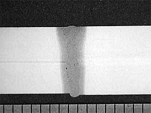
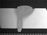
Using these conditions, the joint gap was increased until the weld profile was no longer satisfactory. Sections of the autogenous laser welds made on a zero joint gap and on a 0.2mm joint gap can be seen in Figure 1. These welds were assessed to have no imperfections greater than level D (moderate), in BS EN ISO 13919-1:1997. At 0.3mm gap (and above), lack of fusion the welds unacceptable to BS EN ISO 13919-1:1997. If quality level C and B (intermediate and stringent) are required, in which the maximum acceptable incompletely filled groove is 0.5mm, the maximum allowed joint gap using autogenous laser welding is less than 0.25mm.
| a) 0mm joint gap |
b) 0.2mm joint gap |
|
|
|
Fig.1. Cross sections of autogenous CO2 laser welds in 8.0mm C-Mn steel plate produced with 4.0kW laser power and 1.2m/min travel speed.
For laser welding with filler wire it was difficult to obtain fully penetrating welds using 4kW of laser power unless the welding was performed at very low speed of 0.4m/min.
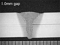
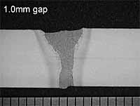
Figure 2 shows sections of welds produced using laser welding with filler wire, in square edge butt joints with 1.5mm gaps. The 4kW laser power was not sufficient to melt the filler wire and produce a full penetration weld at 0.6m/min (
Figure 2a). When the travel speed was decreased to 0.4m/min, the weld became fully penetrating (
Figure 2b). However, imperfections such as lack of fusion can also be seen in this weld.
| a) Travel speed 0.6m/min |
b) Travel speed 0.4m/min |
|
|
|
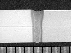
Fig.2. Sections of square edge butt joint welds in 8.0mm C-Mn steel produced with 4.0kW laser power, 1.5mm joint gap and 4.2m/min wire feeding rate.
For laser welding with filler wire it was difficult to obtain fully penetrating welds using 4kW of laser power unless the welding was performed at very low speed of 0.4m/min. Figure 2 shows sections of welds produced using laser welding with filler wire, in square edge butt joints with 1.5mm gaps. The 4kW laser power was not sufficient to melt the filler wire and produce a full penetration weld at0.6m/min ( Figure 2a). When the travel speed was decreased to 0.4m/min, the weld became fully penetrating ( Figure 2b). However, imperfections such as lack of fusion can also be seen in this weld.
The following welding conditions produced fully penetrating laser welds with filler wire on 8mm thickness steel:
- 4kW laser power
- -2.0mm focus position
- 30 litre/min helium coaxial gas
- 10 litre/min helium plasma suppression gas, trailing laser beam, impingement point 1mm ahead of the beam
- 1.2mm diameter C-Mn steel filler wire, leading the laser beam, impingement point 2mm ahead of the beam
- 0.4m/min travel speed and 4.2m/min wire feed speed for square edge butt joints with 1.5mm joint gap
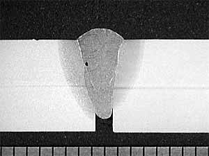
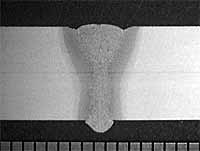
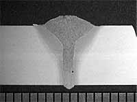
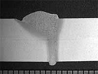
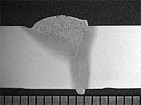
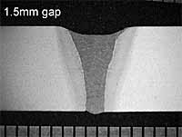
In hybrid laser MAG welding, regarding the effect of arc push/pull direction, the MAG pulling hybrid process gave deeper penetration than the MAG pushing hybrid process, as seen in Figure 3a and 3b. In addition, the section produced using the MAG pushing process showed a 'wine glass' profile with a narrow root and large cap, whereas the profile produced using the MAG pulling laser hybrid process exhibited more of a 'wedge' shape with a slightly wider root and smaller cap. Figure 3c and 3d, are cross sections of welds produced with the laser beam and MAG torch positioned side by side, i.e. with a transverse process separation. These sections are very similar, with a wide and asymmetrical top bead, indicating the laser was responsible for the penetration and the MAG for the deposition of filler material. The cross sections in Figure 3e and 3f were taken from positions with the laser beam and MAG torch side by side but with one source slightly behind the other. These sections were of similar geometry to those shown in Figure 3c and 3d.
| a) MAG pulling, 1.5mm longitudinal separation |
b) MAG pushing, 1.5mm longitudinal separation |
c) Laser/MAG side by side with 1.5mm transverse process separation |
 |
 |
 |
d) Laser/MAG side by side with 1.5mm transverse separation |
e) Laser/MAG oriented at 45° with 1.5mm separation |
f) Laser/MAG oriented at 45° with 1.5mm separation |
 |
 |
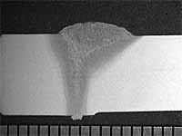 |
Fig.3. Cross sections of welds produced using different arc push/pull configurations on 8mm thick steel with 4.0kW laser power, 1.0m/min travel speed, 4.0kW MAG power and 5.8m/min wire feed speed.
Based on the results above, it was decided only to investigate processing for zero gap butt joints in the direction of the arc/laser separation. Trials were initially conducted to establish conditions to achieve fully penetrating welds in zero gap square edge butt joints, using various process separations, for both arc pushing and pulling variations. It was noticed that when using MAG pulling, the most stable conditions were achieved when the process separation was between 1.5 and 2mm. For MAG pushing, the best results were achieved with zero separation between the two processes. The MAG pulling process had slight advantages over the MAG pushing process in terms of weld profile and gap bridging ability. The following conditions were found to give the best combination of process stability and weld profile, for hybrid CO2 laser MAG welds in 8mm thickness steel plate, using a square edge, zero gap butt joint:
- 4kW laser power
- -2.0mm focus position
- 30 litre/min helium coaxial gas
- 12 litre/min 55%He-43%Ar-2%CO2 welding gas through the MAG torch
- MAG pulling configuration with 1.5-2.0mm process separation or MAG pushing configuration with no process separation
- 1.2mm diameter C-Mn steel welding wire
- Pulsed MAG metal transfer
- 4kW MAG power (22V, 179A and 5.8m/min wire feed rate)
- 1.0m/min welding speed
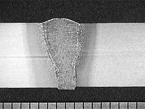
The same conditions developed on zero-gap butt joints were used for completing welds with a varying gap (0mm gap at the start and 2.0mm gap at the end) along the weld length. The transverse sections made along such a weld at various joint gaps are shown in Figure 4a-f the geometrical features of these weld sections are summarised in Figure 4g.
Fig.4g) Graph showing the measured excess weld metal and incompletely filled groove, based on the result above. The measured values are compared to values defined in BS EN ISO 13919-1:1997
It was possible, under the varying joint gap conditions, to produce fully penetrating, square edge butt joints, without the weld pool falling through, even for the largest gap, i.e. 2.0mm. However, the geometrical features of the weld profiles produced at different positions were different. With a small gap (<1.0mm), the transfer of filler material via the arc caused a build-up of metal on top of the weld, leaving the weld with an excess weld metal profile. The height of the excess weld metal was approximately 1.0mm at the beginning of the weld ( Figure 4a), corresponding to a quality level B (stringent) defined in BS EN ISO 13919-1:1997. The amount of excess weld metal decreased with the increase of joint gap and effectively reached zero at a joint gap of about 0.9mm( Figure 4c). An incompletely filled groove then became evident which was within the limit (0.5mm) of quality level B (stringent) when the joint gap was between 0.9 and 1.2mm. By a joint gap of 1.4mm, the incompletely filled groove was close to the limit (1.0mm) set for quality class D (moderate) in BS EN ISO 13919-1:1997 ( Figure 4g). For a joint gap above 1.5mm, the weld became unacceptable because the incompletely filled groove was beyond the limit defined in BS EN ISO 13919-1:1997.
The results indicate that when the hybrid CO2 laser MAG welding process was used to produce butt joints in 8mm thick C-Mn steel, conditions optimised for zero gap could be used up to a maximum joint gap of 1.2mm, if the stringent quality level B is required. This could be extended to 1.4mm if the moderate (D) quality level is required due to changes to the incompletely filled groove.
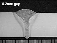
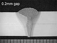
Figure 5 shows cross-sections of welds produced on butt joints made using a series of constant joint gaps of 0.2mm, 1.0mm and 1.5mm, using the welding conditions developed for zero gap butt joints, with a MAG pushing, zero process separation and with a MAG pulling 2.0mm process separation. These results also indicated that gaps up to about 1.4mm could be tolerated by the hybrid CO2 laser MAG welding process in 8mm thick steel, without the weld profile becoming unacceptable.
| a) 0.2mm joint gap, MAG pushing, 0 mm separation |
b) 0.2mm joint gap, MAG pulling 2.0mm separation |
c) 1.0mm joint gap, MAG pushing, 0 separation |
 |
 |
 |
| d) 1.0mm joint gap, MAG pulling, 2.0mm separation |
e) 1.5mm joint gap, MAG pushing, 0 separation |
f) 1.5mm joint gap, MAG pulling, 2.0mm separation |
 |
 |
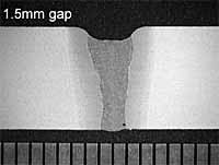 |
Fig.5. Sections of hybrid laser/MAG welds on square edge butt joints produced with 4kW laser power, 4kW MAG power, 5.8m/min wire feeding rate, at 1.0m/min travel speed and constant joint gaps: a) 0.2mm joint gap, MAG pushing, 0 mm separation
Fig.7. Sections of hybrid laser/MAG welds in 8mm thickness C-Mn steel produced with 4kW laser power, 4kW MAG power, 9.0m/min wire feed speed, MAG pulling, 1.5mm separation and 1.0m/min travel speed, on a square edge butt joints with joint gap varying from 2.0mm at the start to 0mm at the end
4. Discussion
It is apparent from this work that the hybrid CO2-MAG welding process had advantages over autogenous CO2 laser and laser with filler wire welding processes, in terms of gap bridging ability. The difference is related to the characteristics of the hybrid process and the interactions between the laser and the arc process.
For autogenous laser welding, the width of gap that can be tolerated is usually of the order of the focused diameter of the laser beam. In this work, it was noticed that joint gaps up to only 0.3mm could be tolerated before the level of fusion became unacceptable. This dimension is similar to the focused spot diameter of the laser used. The laser beam simply passes through the gap if the joint gap is larger than 0.3mm.
Laser welding with filler wire has advantages over the autogenous laser process when bridging gaps with a reduced welding speed. Results of the current work show that it was possible to produce acceptable welds on butt joints with a joint gap up to 1.5mm, in 8mm thickness C-Mn steel, using a 4.0kW laser power at a very low speed of 0.4m/min. Because the travel speed was very slow, plasma suppression techniques were required to maintain an acceptable weld. The procedures for setting up laser welding with filler wire were also complicated compared to those for autogenous laser welding. Joint misalignments need to be minimised to achieve consistent weld quality. To aid the positioning of filler wire into the leading edge of the laser weld pool, a gap of just larger than the filler wire diameter is recommended to encourage the filler wire to enter the weld correctly. Adding filler wire to joint gaps that are much narrower than the wire diameter was difficult to achieve. In general, precise control of the wire into the edge of the keyhole is essential for this process.
The current hybrid CO2 laser MAG welding work on 8mm thickness steel has shown that the hybrid process has a much larger tolerance to joint gaps, compared to the laser alone and laser welding with filler wire process. Gaps greater than 0.3mm resulted in top bead sinkage and subsequent loss of fusion in the laser alone process. The hybrid CO2 laser MAG welding process could accommodate joint gaps between 0mm and 1.4mm (variable or constant) on square edge butt joints in 8mm thickness C-Mn steel, whilst maintaining a class B (stringent) quality level, without adjusting the welding parameters. Larger gaps up to 1.6mm could also be tolerated by increasing the wire feed speed or reducing the travel speed. This large gap bridging capability of the hybrid laser MAG welding process should therefore broaden the range of tolerance with regard to edge preparation quality and relax production constraints, in a range of industrial sectors, and should be of particular interest in the industries which use heavy sections, such as ship building, where steels up to 20mm in thickness are used and where the fit-up tolerances required by autogenous laser welding are difficult to fulfil.
Work in this project also showed that the hybrid welding process could be conducted at a speed similar to that of autogenous laser welding but much higher than that for the laser with filler wire process. With 4kW of laser power and4kW of MAG power, it was possible to achieve fully penetrating hybrid welds on 8mm thickness plate at 1.0m/min, whereas the maximum travel speed achieved for laser welding with filler wire using the same laser power, was 0.4m/min. The high travel speed of the hybrid laser MAG process might be due to the synergy of the arc and the laser in the combined weld pool. The hybrid laser-arc process should be considered for production applications where changing gaps are expected, employing on-line gap measurement to adaptively control the welding process.
5. Conclusions
The gap bridging capability of the hybrid laser-arc welding process has been compared with autogenous laser welding and laser welding with filler wire, on butt joints in 8mm thickness C-Mn steel, using a fast axial CO2 laser combined in a single weld pool with a MAG welding process. The main conclusions drawn from this work are:
- The hybrid process could be conducted at a much higher speed than when laser welding with filler wire, using the same work piece laser power. Class B welds could be produced at 1.0m/min using the hybrid CO2 laser MAG welding process, whereas the maximum travel speed achieved for the process of laser welding with filler wire was only 0.4m/min.
- The hybrid process had a much larger gap bridging capability than either autogenous laser welding or laser welding with filler wire. With the hybrid process, it was possible to weld joint gaps that were four times as wide as those tolerated by the autogenous laser welding process, at a similar welding speed. Acceptable welds could be produced on butt joints with a gap up to 1.4mm, without adjusting the welding parameters, when using hybrid welding. Larger joint gaps up to 1.6mm could also be accommodated by adjusting the wire feed speed or the travel speed, with other welding parameters remaining unchanged.
- There was no significant difference between the MAG pushing and MAG pulling hybrid CO2 laser-arc configuration, on the weld geometry and gap bridging capability, if there was no separation between the two process. However, when a separation was introduced between the impingement points of the laser beam and the MAG process, the MAG pulling configuration gave deeper penetration than the MAG pushing configuration and the weld geometry was also different. The welds produced using the MAG pulling configuration exhibited the typical 'wine-glass' shaped weld profile, with a narrow root and a large cap, whereas the welds produced using the MAG pushing configuration had a more wedge shaped profile.
- In the hybrid welding process, the wire feed speed or the travel speed could potentially be used as a real-time adaptive control parameter to compensate for a variation in joint gap, whilst still maintaining a consistent weld quality.
6. References
- Huntington C.A. and Eagar T.W.: Laser welding aluminium and aluminium alloys. Welding Journal, 1983 62 (4) 105s-107s.
- Norris I.M.: High power laser welding of structural steels - current status. Advances In Joining and Cutting Processes. Proceedings, International Conference, Harrogate, UK, 30 October-2 November 1989, 196-218.
- Dilthey U. and Wieschemann A.: Advantages in laser-arc hybrid welding. Proceedings of Conference SOJOM, 2000.
- Downs D.L. and Mulligan S.J.: Hybrid CO2 laser-MAG welding of carbon steel - a literature review and initial study. TWI Members Report 739/2002.
- Matsuda J., Utsumi A., Katsmura M., Hamasaki M. and Nagata S.: TIG or MIG arc augmented laser welding of thick mild steel plate'. Joining and Materials 1988 (1) 31-34.
- Tusek J. and Suban M.: Hybrid welding with arc and laser beam. Science and Technology of Welding and Joining 1999, 4 (5) 308-311.
- Abe N., Agano Y., Tsukamoto M., Makino T., Hayashi M. and Kurosawa T.: High speed welding of thick plates using a laser-arc combination system. Transactions of JWRI 1997, 26 (1) 69-75.
- Dilthey U. and Keller H.: Prospects in laser GMA hybrid welding steel. Laser 2001, Munich.
- Blundell N.: Arc takes laser welding into new territory. Materials World, September 1998.
- Olivier C.A. and Gerritsen C.H.J.: Study into the use of process gasses in high power Nd:YAG laser welding of C-Mn and stainless steels. TWI Members Report 723/2001.
- BS EN 440: 1995: Welding consumables - Wire electrodes and deposits for gas shielded metal arc welding of non alloy and fine grain steels - classification.
- BS EN ISO 13919-1:1997 Welding - Electron and laser beam welded joints - Guidance on quality levels for imperfections. Part 1. Steel.